engine control unit

A control device and engine technology, applied to engine components, combustion engines, machines/engines, etc., can solve problems such as engine drive and stop, and achieve the effects of restraining power consumption, restraining capacity reduction, and restraining pistons from crossing top dead center

Active Publication Date: 2016-03-09
HONDA MOTOR CO LTD
View PDF5 Cites 1 Cited by
  • Summary
  • Abstract
  • Description
  • Claims
  • Application Information

AI Technical Summary

Problems solved by technology

When the capacity of the battery is temporarily insufficient, when the idling stop control is executed, there will be troubles such as stopping the driving of the engine.

Method used


Image

  • engine control unit
  • engine control unit
  • engine control unit

Examples


Embodiment Construction

[0033] Hereinafter, the engine control device according to the present invention will be described in detail with reference to the drawings according to preferred embodiments.

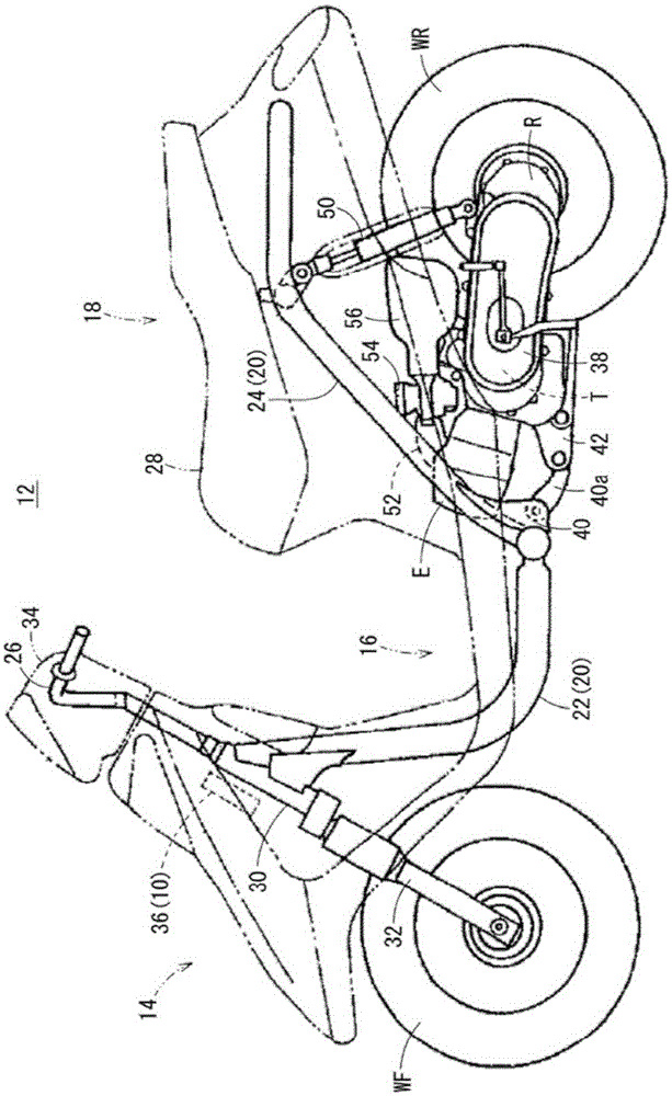
[0034] Such as figure 1 As shown, the engine control device 10 according to one embodiment of the present invention is mounted on a scooter-type motorcycle 12 (hereinafter also simply referred to as a scooter 12 ). In addition, the engine control device 10 of the present invention is not limited to being mounted on the scooter 12, but can also be applied to other types of motorcycles or automobiles.

[0035] A front body 14 and a rear body 16 of the scooter 12 are connected via a low-floor floor 18 . The body frame 20 of the scooter 12 is composed of a down tube 22 bent and extended to the front body part 14 and the low-floor bottom 18, and a main pipe connected to the rear part of the down tube 22 so that the body rear part 16 extends rearward and obliquely upward. 24 and constituted. Furthermore, ...


PUM


Abstract

Object To detect the status of a battery by utilizing reverse rotation drive of a crankshaft at the time of engine start-up. Solving Means An engine control device (10) has an ECU (36) configured to perform, in starting an engine (E), swing-back control in which a motor (70) driven based on a supply current from a battery (96) drives a crankshaft (48) in a reverse rotation direction, and after the drive in the reverse rotation direction, drives the crankshaft (48) in a normal rotation direction. The ECU (36) has: a supply controller (128) configured to set a duty ratio of the supply current used in a first time period (T1) to a value larger than that used in a second time period (T2), the first time period (T1) extending from a time point at which the reverse rotation of the crankshaft (48) is started to a predetermined time point, the second time period (T2) extending from the predetermined time point; and a battery status determination unit (126) configured to determine a status of the battery (96) based on a state of voltage of the battery (96) in the first time period (T1).

Description

technical field [0001] The present invention relates to an engine control device for driving a crankshaft of an engine in forward rotation and in reverse rotation based on control of an electric motor. Background technique [0002] Usually, when the engine is started, a forward driving torque is transmitted from the electric motor to the crankshaft to perform an initial rotation, and this rotation is transformed into rotation of the crankshaft driven by its own force due to combustion of fuel. In addition, it is known that when the motor is rotated, the piston inside the engine will pass the compression top dead center due to the inertial force, so it is necessary to drive the crankshaft in the reverse direction before driving the crankshaft in the forward direction to extend the compression to the top dead center. Swingback (swingback) control of an assist distance to a dead center (refer to Patent Document 1). [0003] The engine start control device disclosed in Patent D...

Claims


Application Information

Patent Timeline
Patent Type & Authority Patents(China)
IPC IPC(8): F02N11/08
CPCF02N11/0825F02N19/005F02N2200/061F02N2200/063F02N2300/106F02N2300/108G01R31/007G01R31/382Y02T10/40
Inventor 大泽俊章竹繁彻朗西敦史高山庆士
Owner HONDA MOTOR CO LTD
Why Eureka
Try Eureka