
Microwave oven

A microwave oven and wave plate technology, applied in the microwave oven field, can solve problems such as affecting the user's comfort, reduce the life of the stirring plate, etc., and achieve the effects of improving market competitiveness, improving service life, and rotating smoothly

Active Publication Date: 2015-08-12
GUANGDONG MIDEA KITCHEN APPLIANCES MFG CO LTD +1
View PDF7 Cites 3 Cited by
  • Summary
  • Abstract
  • Description
  • Claims
  • Application Information

AI Technical Summary

Problems solved by technology

Since the stirring shaft is only connected to the motor shaft by the square hole of the shaft body, and it is a clearance fit, the stirring shaft will swing slightly when it rotates, causing the blade to fluctuate up and down when the stirring plate rotates, and the upper ceramic plate and U plate Friction or scratching, and abnormal noise, affect the user's comfort, and also reduce the life of the stirring plate

Method used


Image

  • Microwave oven
  • Microwave oven
  • Microwave oven

Examples


Embodiment Construction

[0024] In order to understand the above-mentioned purpose, features and advantages of the present invention more clearly, the present invention will be further described in detail below in conjunction with the accompanying drawings and specific embodiments. It should be noted that, in the case of no conflict, the embodiments of the present application and the features in the embodiments can be combined with each other.

[0025] In the following description, many specific details are set forth in order to fully understand the present invention. However, the present invention can also be implemented in other ways different from those described here. Therefore, the protection scope of the present invention is not limited by the specific details disclosed below. EXAMPLE LIMITATIONS.

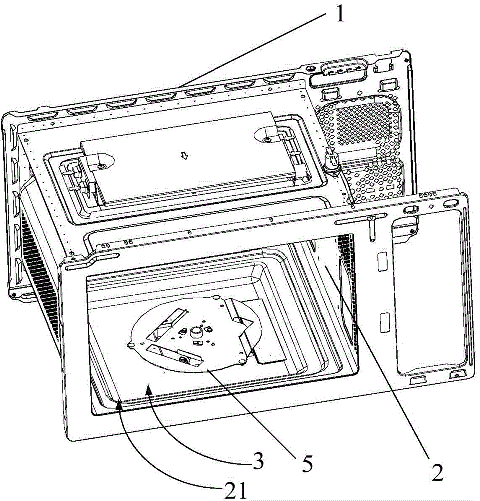
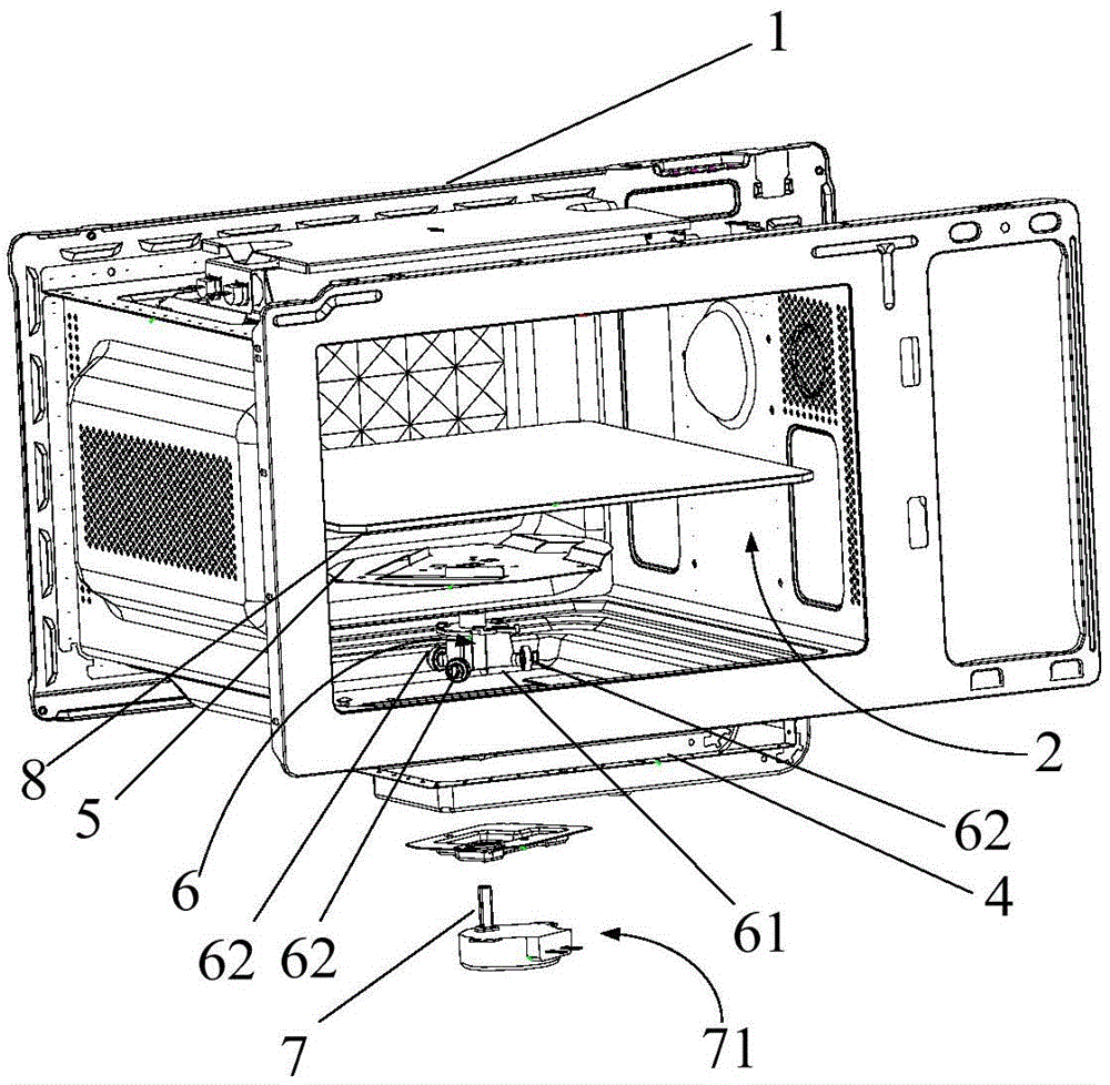
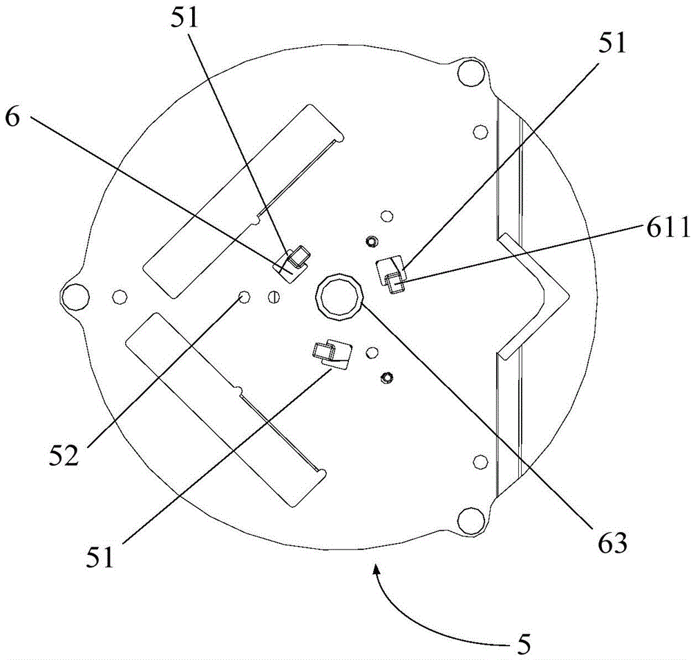
[0026] Refer below Figure 1 to Figure 4 A microwave oven according to some embodiments of the invention is described.

[0027] Such as figure 1 with figure 2 As shown, the microwave oven provid...


PUM


Abstract

The invention provides a microwave oven. The microwave oven comprises a shell, an inner container, a wave transmitting plate, a driving device, a wave guiding tube and a wave stirring sheet. The baseboard of the inner container is arranged in a downward depressed mounting groove, and the wave stirring sheet is connected with the output shaft of the driving device through a stirring shaft; and the stirring shaft comprises a first connecting portion and slide supporting portions, the first connecting portion is connected with the output shaft and the wave stirring sheet respectively, and the slide supporting portions are connected with the first connecting portion, are supported on the bottom wall of the mounting groove, and slide on the bottom wall of the mounting groove. The stirring shaft is provided with the slide supporting portions, so the stirring shaft realizes stable rotation without swinging in order to make the rotation of the wave stirring sheet stable, so deviant noise generated by friction or scratching of the wave stirring sheet and the wave transmitting plate and the inner container is avoided to improve the use comfort level of a user, and the service life of the wave stirring sheet is prolonged to improve the market competitiveness of products.

Description

technical field [0001] The invention relates to the field of household appliances, in particular to a microwave oven. Background technique [0002] At present, the microwave stirring device used in the existing microwave oven includes a stirring plate, a stirring shaft and a stirring motor. The upper end of the stirring shaft is large and the lower end is small. The upper end is connected to the stirring plate through a buckle, and the lower end shaft has a square hole, which is connected to the motor shaft. When working, the stirring motor drives the stirring shaft to rotate, and the stirring shaft drives the stirring plate to rotate. Stir. Since the stirring shaft is only connected to the motor shaft by the square hole of the shaft body, and it is a clearance fit, the stirring shaft will swing slightly when it rotates, causing the blades to fluctuate up and down when the stirring plate rotates, and the upper ceramic plate and U plate Friction or scratching occurs, and ab...

Claims


Application Information

Patent Timeline
Patent Type & Authority Applications(China)
IPC IPC(8): F24C7/02F24C7/06
CPCH05B6/745H05B6/80
Inventor 赵超一黄兴忠李明星
Owner GUANGDONG MIDEA KITCHEN APPLIANCES MFG CO LTD
Learn More