freezer

A refrigeration device and refrigerant technology, which is applied in the direction of refrigerators, refrigeration components, refrigeration and liquefaction, etc., can solve the problems of the decrease of the performance coefficient, the increase of the specific enthalpy at the entrance of the evaporator, and the decrease of the refrigeration capacity, etc., and achieve the effect of improving the coefficient of performance

Active Publication Date: 2018-04-20
PANASONIC INTELLECTUAL PROPERTY MANAGEMENT CO LTD
View PDF8 Cites 0 Cited by
  • Summary
  • Abstract
  • Description
  • Claims
  • Application Information

AI Technical Summary

Problems solved by technology

[0004] On the other hand, for a refrigeration device installed in an evaporator such as a showcase to cool the inside of the cabinet by using heat absorption, the temperature at the outlet of the gas cooler is high due to the high temperature of the outside air (the temperature of the heat source on the side of the gas cooler). When the temperature of the refrigerant increases, the specific enthalpy at the inlet of the evaporator increases, so there is a problem that the refrigeration capacity drops significantly
At this time, if the discharge pressure (high pressure side pressure) of the compression mechanism is increased in order to ensure the refrigeration capacity, the compression power will increase and the coefficient of performance will decrease.

Method used


Image

  • freezer
  • freezer
  • freezer

Examples


Embodiment Construction

[0090] (1) Structure of refrigeration unit R

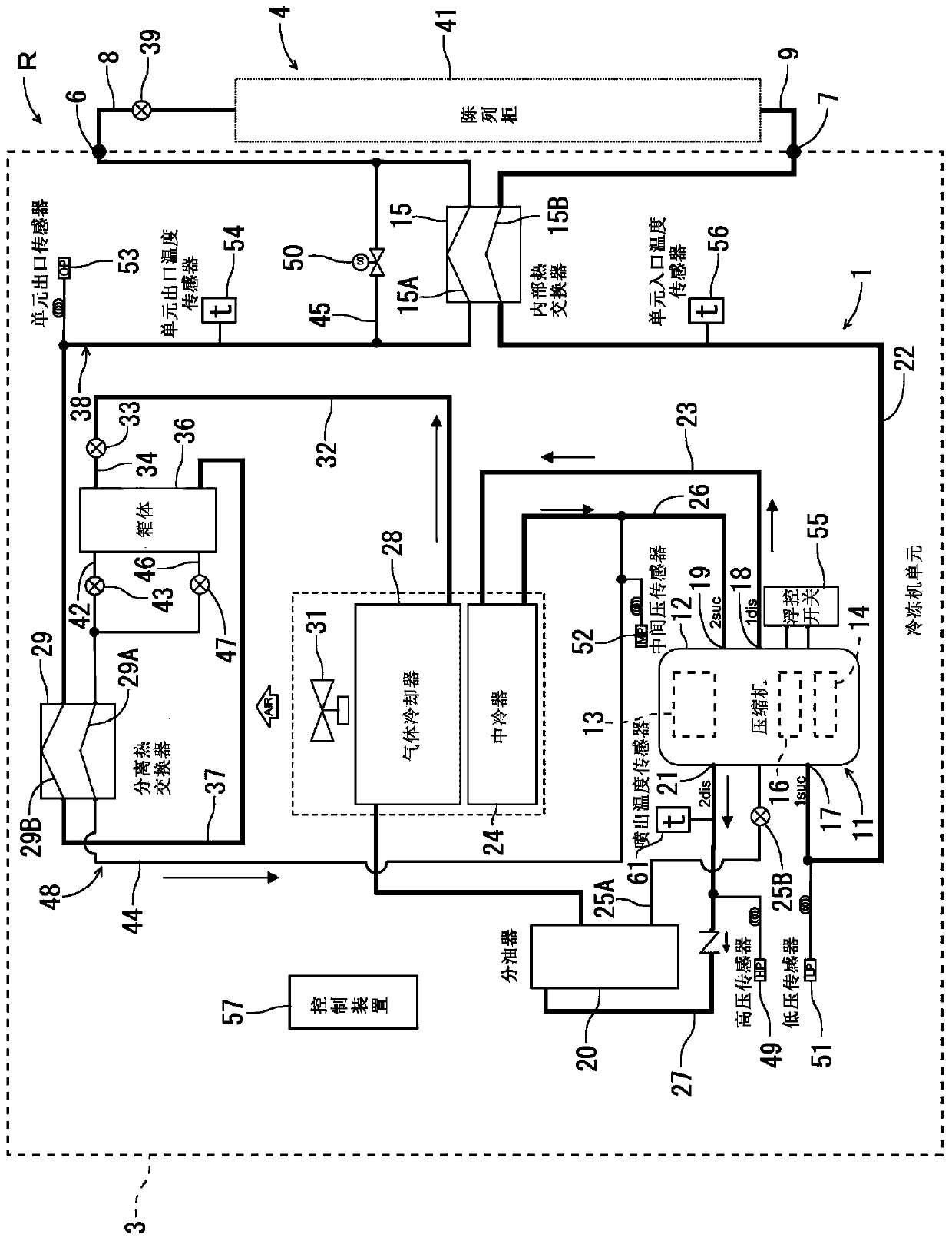
[0091] Hereinafter, embodiments of the present invention will be described with reference to the drawings. figure 1 It is a refrigerant circuit diagram of the refrigerating apparatus R according to one embodiment of the present invention. The refrigerating apparatus R in this embodiment includes a refrigerating machine unit 3 installed in an equipment room of a store such as a supermarket, and one or more (only one is shown in the drawing) display cabinets 4 installed in a counter of the store. These refrigerator units 3 and showcases 4 are connected by refrigerant pipes (liquid pipes) 8 and refrigerant pipes 9 via unit outlets 6 and unit inlets 7 to form a predetermined refrigerant circuit 1 .

[0092] The refrigerant circuit 1 uses, as a refrigerant, carbon dioxide (R744) whose refrigerant pressure on the high-pressure side is equal to or higher than its critical pressure (supercritical). This carbon dioxide refrigerant is a n...


PUM


Abstract

The present invention provides a refrigerating device capable of protecting a compression mechanism from an increase in the pressure of the high pressure side when the high pressure side reaches a supercritical pressure, and ensuring a stable refrigerating capacity that is not affected by the temperature of the outside air. The freezing device comprises: an electric expansion valve (33), connected to the downstream side of the gas cooler (28) and the upstream side of the electric expansion valve (39); a casing (36), connected to its downstream side and the electric expansion valve ( 39) on the upstream side; the separation heat exchanger (29) is arranged on its downstream side and the upstream side of the electric expansion valve (39); the auxiliary circuit (48) makes the refrigerant in the box pass through the electric expansion valve (43, 47 ) into the intermediate pressure part of the compressor (11) after flowing into the separation heat exchanger; After heat exchange, it flows into the electric expansion valve (39), and the control device (57) adjusts the high-pressure side pressure of the refrigerant circuit on the upstream side through the electric expansion valve (33).

Description

technical field [0001] The invention relates to a refrigerating device whose refrigerant circuit is composed of a compression mechanism, a gas cooler, a main throttling mechanism and an evaporator, and the high-pressure side reaches supercritical pressure. Background technique [0002] In the past, this type of refrigeration device constituted a refrigeration cycle by a compression mechanism, a gas cooler, and a throttling mechanism. The refrigerant evaporates, and the surrounding air is cooled by the evaporation of the refrigerant at this time. In recent years, Freon-based refrigerants have been gradually no longer used in such refrigerating devices due to natural environmental problems and the like. Therefore, the use of carbon dioxide, which is a natural refrigerant, as a substitute for Freon refrigerants is being developed. It is known that this carbon dioxide refrigerant is a refrigerant having a severe high-pressure difference and has a low critical pressure, and tha...

Claims


Application Information

Patent Timeline
Patent Type & Authority Patents(China)
IPC IPC(8): F25B1/00F25B41/06F25B49/02F25B41/34
CPCF25B1/00F25B49/02F25B41/30F25B9/008F25B2309/061
Inventor 仓田裕辅木屋丰明三原一彦八藤后裕志加藤光洋
Owner PANASONIC INTELLECTUAL PROPERTY MANAGEMENT CO LTD
Why Eureka
Try Eureka