Freezing apparatus

A refrigeration device and refrigerant technology, applied in refrigerators, refrigeration components, refrigeration and liquefaction, etc., can solve problems such as increased compression power, large enthalpy change at the entrance of the evaporator, and decreased coefficient of performance, so as to reduce dryness Effect

Active Publication Date: 2015-08-12
PANASONIC INTELLECTUAL PROPERTY MANAGEMENT CO LTD
View PDF8 Cites 0 Cited by
  • Summary
  • Abstract
  • Description
  • Claims
  • Application Information

AI Technical Summary

Problems solved by technology

[0004] On the other hand, for a refrigeration device installed in an evaporator such as a showcase to cool the inside of the cabinet by using heat absorption, the temperature at the outlet of the gas cooler is high due to the high temperature of the outside air (the temperature of the heat source on the side of the gas cooler). When the temperature of the refrigerant increases, the specific enthalpy at the inlet of the evaporator increases, so there is a problem that the refrigeration capacity drops significantly
At this time, if the discharge pressure (high pressure side pressure) of the compression mechanism is increased in order to ensure the refrigeration capacity, the compression power will increase and the coefficient of performance will decrease.

Method used


Image

  • Freezing apparatus
  • Freezing apparatus
  • Freezing apparatus

Examples


Embodiment 1

[0076] (1) Structure of refrigeration unit R

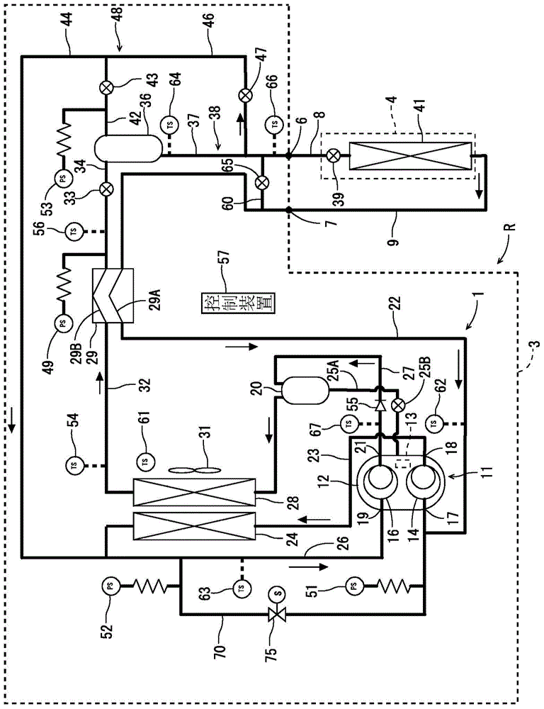
[0077] figure 1 It is a refrigerant circuit diagram of the refrigerating apparatus R according to one embodiment of the present invention. The refrigerating apparatus R in this embodiment includes a refrigerating machine unit 3 installed in an equipment room of a store such as a supermarket, and one or more (only one is shown in the drawing) display cabinets 4 installed in a sales floor of the store. These refrigerator units 3 and showcases 4 are connected by refrigerant pipes (liquid pipes) 8 and refrigerant pipes 9 via unit outlets 6 and unit inlets 7 to form a predetermined refrigerant circuit 1 .

[0078] The refrigerant circuit 1 of the embodiment uses carbon dioxide (R744) whose refrigerant pressure on the high-pressure side is equal to or higher than its critical pressure (supercritical) as a refrigerant. This carbon dioxide refrigerant is a natural refrigerant that is friendly to the global environment and considers flam...

Embodiment 2

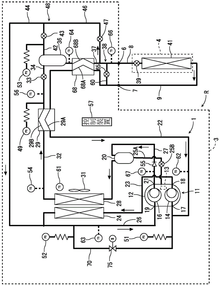
[0141] Next, refer to image 3 and Figure 4 Another embodiment of the present invention will be described. also, image 3 and Figure 4 , labeled with figure 1 and figure 2 Parts with the same reference numerals are the same or have the same function. In the case of this example, in figure 1 The internal heat exchanger 68 is added to the refrigerant circuit 1. This internal heat exchanger 68 is provided in the refrigerant circuit 1 on the downstream side of the accumulator 36 and on the upstream side of the electric expansion valve 39 (primary throttling mechanism).

[0142] The internal heat exchanger 68 has a first flow path 68A and a second flow path 68B, and the first flow path 68A is interposed in the refrigerant introduction pipe 22 between the connection point with the bypass circuit 60 and the first flow path 29A of the heat exchanger 29 Among them, the second flow path 68B is interposed in the accumulator outlet pipe 37 before branching off from the liquid p...


PUM


Abstract

The invention provides a freezing apparatus. When the high pressure side is up to a supercritical pressure, a refrigerant flows out of an air cooler is cooled by a refrigerant flows out of an evaporator. The freezing apparatus comprises a heat exchanger (29) that is set at the downstream side of the air cooler (28) and the upstream side of an electric expansion valve (33); a bypass circuit (60) that is connected in parallel to a serial loop of an electric expansion valve (39) and the evaporator (41); an electric expansion valve (65) that is set in the bypass circuit; and a control apparatus (57) that helps the refrigerant flowed out of the evaporator and sucked into a compressor (11) flow into a first path (29A) of a heat exchanger (29), and helps the refrigerant flowed from the air cooler into the electric expansion valve (33) flow into a second path (29B) of the heat exchanger (29). In this way, the refrigerant flows in the first path (29A) of the heat exchanger (29) is is used to cool the refrigerant in the second path (29B) of the heat exchanger (29).

Description

technical field [0001] The invention relates to a refrigerating device whose refrigerant circuit is composed of a compression mechanism, a gas cooler, a main throttling mechanism and an evaporator, and the high-pressure side reaches supercritical pressure. Background technique [0002] In the past, this type of refrigeration device constituted a refrigeration cycle by a compression mechanism, a gas cooler, and a throttling mechanism. The refrigerant evaporates, and the surrounding air is cooled by the evaporation of the refrigerant at this time. In recent years, Freon-based refrigerants have been gradually no longer used in such refrigerating devices due to natural environmental problems and the like. Therefore, the use of carbon dioxide, which is a natural refrigerant, as a substitute for Freon refrigerants is being developed. It is known that this carbon dioxide refrigerant is a refrigerant having a severe high-pressure difference and has a low critical pressure, and tha...

Claims


Application Information

Patent Timeline
Patent Type & Authority Applications(China)
IPC IPC(8): F25B1/00F25B41/06F25B41/34
CPCF25B1/005F25B41/34F25B41/31Y02B30/70
Inventor 冈村隼次轰笃
Owner PANASONIC INTELLECTUAL PROPERTY MANAGEMENT CO LTD
Why Eureka
Try Eureka