
An automatic installation device for bullet anti-channeling hooks

An automatic installation and bullet technology, applied in the direction of ammunition supply, weapon accessories, offensive equipment, etc., can solve the problems of insufficiency of installation methods, complicated installation operations, time-consuming and laborious, etc., to reduce the workload and difficulty of the participants, and improve the loading. Efficiency, Difficulty Reduction, and Fixed Time Effects

Active Publication Date: 2016-05-25
THE GENERAL DESIGNING INST OF HUBEI SPACE TECH ACAD
View PDF6 Cites 0 Cited by
  • Summary
  • Abstract
  • Description
  • Claims
  • Application Information

AI Technical Summary

Problems solved by technology

[0004] The existing installation methods have the following problems: (1) The installation operation is complicated, time-consuming and labor-intensive, and requires high operational skills for workers
(2) Terminal guided bullets are generally equipped with pyrotechnics or explosives. To ensure safety, the workload and difficulty of the participants should be reduced as much as possible, but the existing installation methods cannot meet this requirement
(3) In order to improve combat effectiveness, the anti-slip hook time of the bullet should be reduced as much as possible, and the installation process must be simple and reliable, and the existing manual installation method cannot meet this requirement

Method used


Image

  • An automatic installation device for bullet anti-channeling hooks
  • An automatic installation device for bullet anti-channeling hooks
  • An automatic installation device for bullet anti-channeling hooks

Examples


Embodiment Construction

[0029] In order to make the object, technical solution and advantages of the present invention clearer, the present invention will be further described in detail below in conjunction with the accompanying drawings and embodiments. It should be understood that the specific embodiments described here are only used to explain the present invention, not to limit the present invention. In addition, the technical features involved in the various embodiments of the present invention described below can be combined with each other as long as they do not constitute a conflict with each other.

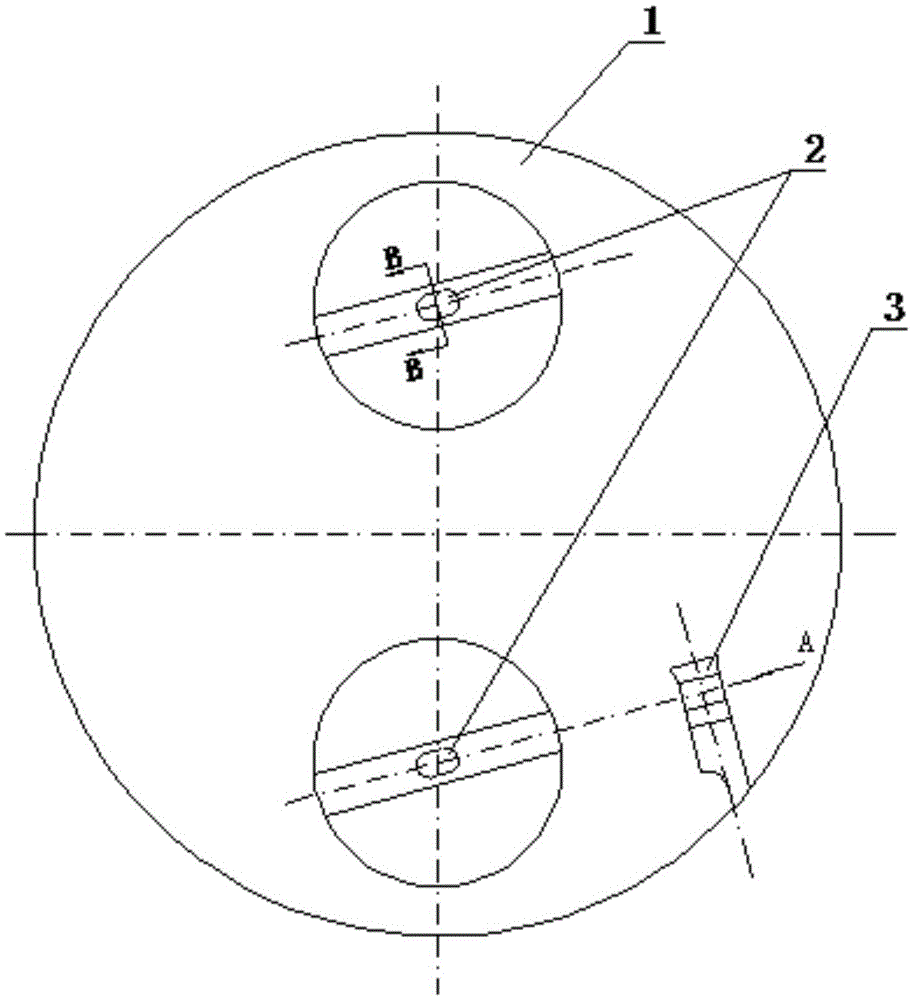
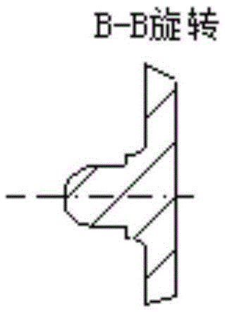
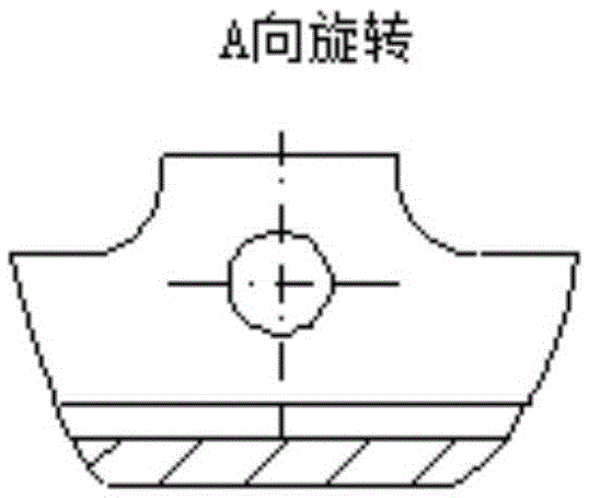
[0030] Fig. 1 (a) is a schematic diagram of the structure of the bottom cover plate of the tail of the bullet in a preferred embodiment of the present invention; Fig. 1 (b) is a sectional view of section B-B in Fig. 1 (a); Fig. 1 (c) is in Fig. 1 (a) View of the anti-channeling hole from A direction; figure 2 It is a schematic diagram of the structure of the support surface of the bullet releas...


PUM


Abstract

The invention discloses an automatic installation device for a bullet accidental discharge prevention hook. The automatic installation device comprises a guide column, a guide groove, an accidental discharge prevention hook assembly and a telescopic ejector rod. The guide column is arranged on a bottom cover plate on the tail portion of a bullet. The central line of the guide column is parallel to the central line of an accidental discharge prevention hole. The guide groove is formed in the supporting face of a bullet release mechanism and used for containing the guide column and making the guide column slide along the guide groove. The accidental discharge prevention hook assembly is arranged on the guide groove and comprises a rotatable accidental discharge prevention pin. The telescopic ejector rod is arranged on a bullet backfill and detachment device and is used for touching, rotating and lifting the accidental discharge prevention pin in the bullet filling process, and retreating to be separated from the accidental discharge prevention pin after filling is completed so that the accidental discharge prevention pin can rotate backwards and fall to the accidental discharge prevention hole under the effect of the gravity of the accidental discharge prevention pin. By means of the automatic installation device, the accidental discharge prevention hook is automatically installed, the installation process is easy and reliable, and workloads and work difficulty of personnel participating in installation can be reduced.

Description

technical field [0001] The invention belongs to the field of terminal-guided bullet loading of sub-guided cluster bullets, and in particular relates to an automatic installation device for bullet anti-channeling hooks. Background technique [0002] After the terminal guided bullet is loaded into the bullet release mechanism, it is necessary to ensure that the bullet is firmly fixed in the bullet release mechanism to ensure that the bullet does not move in the bullet release mechanism when the missile is flying, and to avoid damage to the bullet structure and internal equipment due to vibration or impact . [0003] The fixation of the bullet in the bullet release mechanism includes the radial fixation of the bullet and the axial fixation of the bullet. Since the radial fixation of the bullet involves the release of the bullet when the bullet is separated, it generally needs to be manually installed and fixed after the bullet is loaded into the bullet release mechanism; The a...

Claims


Application Information

Patent Timeline
Patent Type & Authority Patents(China)
IPC IPC(8): F41A9/58
Inventor 汪文龙徐国伟巩立先张正义秦友花
Owner THE GENERAL DESIGNING INST OF HUBEI SPACE TECH ACAD
Learn More