
Implementation method for remote intelligent passage management and control based on screen display height limiting structures

An implementation method and technology of a remote control center, applied in the field of remote intelligent traffic management and control based on the screen display limit height structure, can solve problems such as prone to collision accidents, fire police vehicles cannot pass, special vehicles cannot pass, etc., and the realization method is simple and avoids The effect of the wiring process

Active Publication Date: 2015-08-12
嘉善县临沪新城实业有限公司
View PDF8 Cites 0 Cited by
  • Summary
  • Abstract
  • Description
  • Claims
  • Application Information

AI Technical Summary

Problems solved by technology

[0002] Recently, accidents of vehicles being damaged by the height limiting device have occurred frequently. The main reason is that the height limiting device is an iron rod with a fixed position. The iron rod is prone to collision accidents in the dark and does not know the road conditions, and the fixed position The setting method may easily cause special vehicles to be unable to pass through, for example, in the event of a fire, fire police vehicles cannot pass through, etc.

Method used


Image

  • Implementation method for remote intelligent passage management and control based on screen display height limiting structures
  • Implementation method for remote intelligent passage management and control based on screen display height limiting structures
  • Implementation method for remote intelligent passage management and control based on screen display height limiting structures

Examples


Embodiment Construction

[0032] The present invention will be further described below in conjunction with the accompanying drawings and embodiments.

[0033] like Figure 1 to Figure 5 As shown, this embodiment provides a method for realizing remote intelligent traffic control based on the screen display limit height structure, which is characterized in that it includes the following steps:

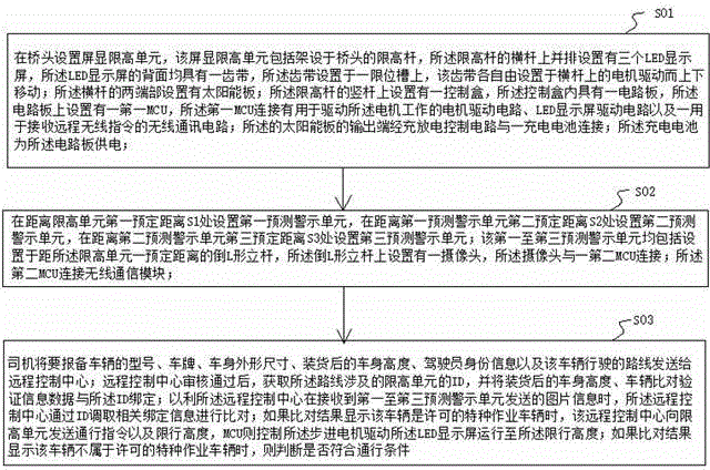
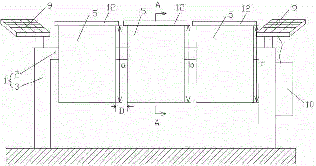
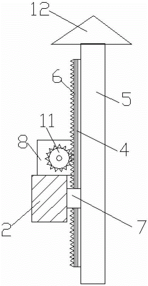
[0034] Step S01: Set the screen display height limit unit at the bridge head, the screen display height limit unit includes the screen display height limit unit, the first predictive warning unit 13, the second predictive warning unit 14 and the third predictive warning unit 15; the remote The control center receives and stores the reporting information of special vehicles; it includes a height-limiting pole 1 erected at the bridgehead, and three LED display screens 5 are arranged side by side on the crossbar 2 of the height-limiting pole, and the back of the LED display screen 5 Each has a toothed belt 6, and t...


PUM


Abstract

The invention relates to an implementation method for remote intelligent passage management and control based on screen display height limiting structures, which comprises a remote control center and a plurality of screen display height limiting structures, wherein each screen display height limiting structure comprises a screen display height limiting unit, a first forecasting and warning unit, a second forecasting and warning unit and a third forecasting and warning unit; the remote control center receives registration information of special vehicles and stores the registration information; each screen display height limiting unit comprises a height limiting rod erected at the bridgehead, a cross rod of each height limiting rod is provided with three LED display screens which are arranged side by side, the reverse side of each LED display screen is provided with a toothed belt, the toothed belt is arranged in a limiting slot, and each tooth belt is driven by a motor arranged on the cross rod to move up and down; and two end parts of the cross rod are provided with solar panels respectively. The implementation method provided by the invention is simple in system structure, and changes a traditional steel type limiting rod structure. The LED display screens act as the limiting rod, thereby not only being capable of playing an effect of limiting passage, but also having an eye-catching warning function.

Description

technical field [0001] The invention relates to the technical field of vehicle height limitation, in particular to a method for realizing remote intelligent traffic management and control based on a screen display height limitation structure. Background technique [0002] Recently, accidents of vehicles being damaged by the height limiting device have occurred frequently. The main reason is that the height limiting device is an iron rod with a fixed position. The iron rod is prone to collision accidents in the dark and does not know the road conditions, and the fixed position The setting method will easily cause special vehicles to be unable to pass through, for example, in case of fire, fire police vehicles will not be able to pass through. Contents of the invention [0003] The purpose of the present invention is to provide a method for realizing remote intelligent traffic management and control based on the height limit structure of the screen display, which can li...

Claims


Application Information

Patent Timeline
IPC IPC(8): G08G1/09
Inventor 苏两河
Owner 嘉善县临沪新城实业有限公司
Learn More