
Conical Rotor DC Permanent Magnet Brake Motor

A technology for braking motors and conical rotors, applied in electric components, controlling mechanical energy, magnetic circuit rotating parts, etc. Weight and other issues, to achieve the effect of reducing manufacturing costs and operating costs, reducing energy loss and mechanical wear, and fast braking

Active Publication Date: 2018-01-05
JIANGXI GONGBU MACHINERY
View PDF6 Cites 0 Cited by
  • Summary
  • Abstract
  • Description
  • Claims
  • Application Information

AI Technical Summary

Problems solved by technology

Due to the need to set the brake separately, it not only increases the equipment manufacturing and operating costs, increases the volume and weight of the equipment, but also reduces the safety and reliability, thus restricting the application of DC permanent magnet motors in cranes and other occasions

Method used


Image

  • Conical Rotor DC Permanent Magnet Brake Motor
  • Conical Rotor DC Permanent Magnet Brake Motor

Examples


Embodiment Construction

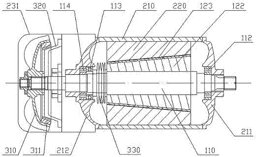
[0008] see figure 1 and figure 2 , The conical rotor DC permanent magnet brake motor disclosed in the present invention includes a casing 210, a main shaft 110, a stator core 220, a rotor core 122 and a brake. The left and right ends of the casing are respectively provided with a left end cover 212 and a The right end cover 211, the main shaft is supported on the left and right end covers through the left and right main shaft bearing shafts 114, 112 to move, the rotor core is located in the stator core, and is fixedly installed on the main shaft. The outer surface of the rotor core and the inner surface of the stator core are conical, a spring thrust device is provided between the left end of the rotor core and the left end cover, and the left end of the main shaft extends outside the left end cover , the brake is a friction brake, including a matching brake piece 310 and a fixed brake piece 320, the brake piece is fixedly installed on the main shaft outside the left end cov...


PUM


Abstract

The invention relates to a conical rotor DC permanent magnet braking motor, which includes a casing, a main shaft, a stator core, a rotor core and a brake. Swimmingly supported on the left and right end covers, a spring thrust device is provided between the rotor core and the left end cover, the brake is a friction brake, including matching dynamic brake parts and customized brake parts, and the dynamic brake parts are fixed on the left end. On the main shaft outside the cover, the custom stopper is fixedly connected with the left end cover, the main shaft speed is 200r / min-900r / min, and the braking torque is 50N / m-2000N / m. The invention enables the DC permanent magnet motor to have a braking function, and when it is used in occasions such as driving a crane reel, the structure of the whole machine can be significantly simplified, the overall volume can be reduced, and the manufacturing cost and operating cost can be reduced.

Description

technical field [0001] The invention relates to a conical rotor DC permanent magnet braking motor. Background technique [0002] The rotor and stator of the existing DC permanent magnet motor are both cylindrical / cylindrical. When energized, the magnetic field of the stator generates a circumferential force on the rotor, which pushes the rotor to rotate, and then drives other equipment to run through the output shaft of the motor. Magnetic motors are small in size, large in output, low in noise, wide in speed regulation range, easy to control, and can be used in several occasions. However, in occasions such as a crane hoisting mechanism, it is required that the actuator should run when the motor is energized. An independent brake is set somewhere, and the brake is powered on and off synchronously with the motor. In the power-off state, the brake is in the braking state, relying on the braking force generated by the spring, etc., and forms a brake under the braking force bet...

Claims


Application Information

Patent Timeline
Patent Type & Authority Patents(China)
IPC IPC(8): H02K7/102H02K1/27H02K1/16H02K3/12
Inventor 彭祖军喻立号
Owner JIANGXI GONGBU MACHINERY
Learn More