Electronic scale
An electronic scale and precision technology, applied in the field of electronic scales, can solve the problems of use, high price, and inability to use it for other purposes, and achieve the effects of preventing damage, being easy to popularize, and reducing costs
- Summary
- Abstract
- Description
- Claims
- Application Information
AI Technical Summary
Problems solved by technology
Method used
Image

Examples
Embodiment 1
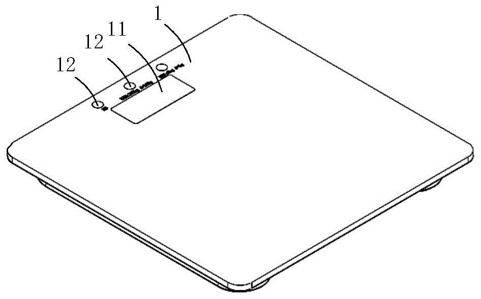
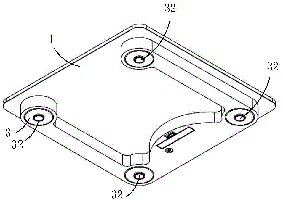
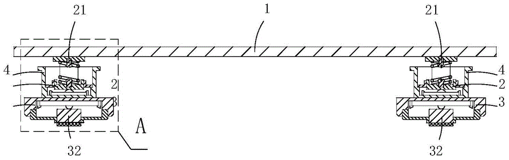
[0055] (Embodiment 1): the present embodiment is a kind of double-precision electronic balance, see Figure 1 to Figure 10 As shown, it includes a loading board 1, a display screen 11, an adjustment switch 12, four first precision weighing assemblies 2 for supporting the loading board, and four first precision weighing assemblies for supporting the loading board and the first precision weighing assembly. The second precision weighing assembly 3, and four force guides 4 for transmitting the pressure on itself to the second precision weighing assembly.
[0056] In the present embodiment, the specific structure of the second precision weighing assembly 3 is as follows: it includes a deck 34 having an accommodation slot 33 and a slot, a second precision load cell 31 arranged in the slot, and abutting on the second The supporting foot 32 on the precision load cell 31, the spring cover 35 that covers the opening at the bottom of the accommodating groove 33 and has a center positioni...
Embodiment 2
[0066] (Embodiment 2): This embodiment is basically the same as Embodiment 1, the difference is: see Figure 11 to Figure 13 As shown, the force guide 4 in this embodiment and the deck 34 in the second precision weighing assembly are integrally made by injection molding. Compared with Embodiment 1, the force guide in this embodiment is no longer separate The bottom wall 41 is provided, but the top wall of the card seat 34 is directly used as the bottom wall 41 of the force guiding member in the first embodiment.
[0067] In addition, the specific structure of the first precision weighing assembly in this embodiment is as follows: it includes a mounting base 27 provided with a slot and an accommodating cavity, and a base that covers the bottom opening of the accommodating cavity in the mounting base and has a central through hole. The elastic cover 28 , the first precision load cell 22 located in the accommodating cavity and snapped into the slot, and the elastic supporting mem...
Embodiment 3
[0071] This embodiment is basically the same as Embodiment 1, the difference is: see Figure 14 to Figure 18 As shown, the top end of the tubular support wall in the force guide is also provided with a square load-bearing plate 5 with four circular support holes 51, which is used as the force guide support part of the force guide in this embodiment. 40. The bottom wall of the carrier board still serves as the force-guiding crimping part 10.
[0072] In this embodiment, in the free state, the upper support member 212 of each elastic support member passes through a corresponding support hole 51 and is bonded and fixed on the bottom wall of the loading board, so that the force guiding crimping portion 10 of the loading board is higher than The force-guiding support part 40 of the force-guiding member; when the weight of the object on the loading plate exceeds a certain level, the loading plate moves down and is crimped on the load-bearing plate, that is, the force-guiding crimpin...
PUM
 Abstract
Description
Claims
Application Information