Hydraulic valve plunger abrasive machining positioning fixture

A technology for grinding and positioning fixtures, which is applied in the direction of grinding workpiece supports, machine tools designed for grinding workpiece rotating surfaces, and manufacturing tools, which can solve the problems of low work efficiency and cumbersome switching operation steps, and improve work efficiency , to ensure the quality of processing, to achieve the effect of accurate positioning

Active Publication Date: 2015-08-19
FACTORY 5721 OF PLA
View PDF6 Cites 9 Cited by
  • Summary
  • Abstract
  • Description
  • Claims
  • Application Information

AI Technical Summary

Problems solved by technology

At present, there are many types of hydraulic valves, and the plunger structures are also various, such as attached figure 1 , figure 2 A hydraulic valve plunger 1 shown has a large circular hole 1-2 perpendicular to the central axis of the plunger at one end, and two sets of cylinders 1-1 matched with the valve body in the middle. A set of inclined plunger working surfaces 1-1-1 are set at both ends of the cylindrical body 1-1 at intervals along the circumference of the outer cylindrical surface, and the plunger 1 cooperates with the valve bo

Method used


Image

  • Hydraulic valve plunger abrasive machining positioning fixture
  • Hydraulic valve plunger abrasive machining positioning fixture
  • Hydraulic valve plunger abrasive machining positioning fixture

Examples


Embodiment Construction

[0031] The present invention will be further described below in conjunction with accompanying drawing.

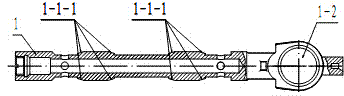
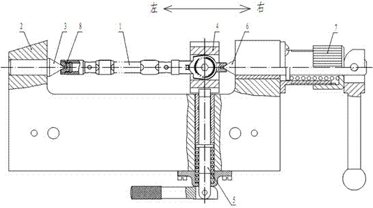
[0032] It should be noted that, in the case of no conflict, the embodiments of the present invention and the features in the embodiments can be combined with each other. In addition, the location words such as "left" and "right" mentioned in the embodiments of the present invention, together with the attached image 3 The left and right directions marked in are the same.

[0033] See Figure 1, figure 2 , image 3 , the positioning fixture for hydraulic valve plunger grinding according to the present invention includes a fixture seat 2, a left top 3, a workpiece positioning sleeve 8, a right top 6, an indexing plate 4 and an indexing plate positioning mechanism 5; the fixture seat 2 It is a "U"-shaped structure, the left top 3 is fixedly installed on the left side wall of its opening end, and the right top 6 that can move left and right is installed on the right side wal...


PUM


Abstract

The invention discloses a hydraulic valve plunger abrasive machining positioning fixture, and belongs to the technical field of abrasive machining devices. The hydraulic valve plunger abrasive machining positioning fixture comprises a fixture base, a left tip, a workpiece positioning sleeve, a right tip, an indexing plate and an indexing plate positioning mechanism. The fixture base is of a U-shaped structure. The left tip is fixedly installed on the left side wall of the opening end of the fixture base, and the right tip capable of moving leftwards and rightwards is installed on the right side wall of the opening end of the fixture base. The left tip and the right tip are located on the same central axis. The workpiece positioning sleeve is installed at the left end of the plunger workpiece and matched with the left tip. The indexing plate is sleeved with a large circular hole of the plunger workpiece. The indexing plate positioning mechanism is installed on a base body of the fixture base of the U-shaped structure and matched with the indexing plate. By means of the hydraulic valve plunger abrasive machining positioning fixture, the plunger workpiece is accurately positioned, the machining quality of the plunger workpiece is ensured, the switching of grinding positions of the plunger workpiece can be rapidly completed, and the work efficiency is improved.

Description

technical field [0001] The invention relates to a positioning fixture, in particular to a positioning fixture suitable for grinding a hydraulic valve plunger, and belongs to the technical field of grinding processing devices. Background technique [0002] The working principle of the hydraulic valve is to use the cooperation of the plunger and the valve body to make the oil circuit connect, disconnect or change the flow direction of the hydraulic oil, so as to realize the start, stop or change the movement direction of the hydraulic actuator and its driving mechanism. At present, there are many types of hydraulic valves, and the plunger structures are also various, such as attached figure 1 , figure 2 A hydraulic valve plunger 1 shown has a large circular hole 1-2 perpendicular to the central axis of the plunger at one end, and two sets of cylinders 1-1 matched with the valve body in the middle. A group of inclined plunger working surfaces 1-1-1 are set at both ends o...

Claims


Application Information

Patent Timeline
IPC IPC(8): B24B41/06
CPCB24B5/35B24B5/36B24B41/06
Inventor 胡树欣张龙飞冯占玉闫永红王奇李冬燕刘强杨强曹增献
Owner FACTORY 5721 OF PLA
Why Eureka
Try Eureka