
Back board mold

A mold and backplane technology, applied in the field of backplane molds, can solve the problems of product quality degradation, low service life, low processing accuracy, etc., and achieve the effects of convenient disassembly and maintenance, low manufacturing cost, and improved uniformity

Inactive Publication Date: 2015-08-19
昆山电子羽电业制品有限公司
View PDF6 Cites 1 Cited by
  • Summary
  • Abstract
  • Description
  • Claims
  • Application Information

AI Technical Summary

Problems solved by technology

This method has many disadvantages. For example, air mixed in the mold cavity due to the lack of a sealing device causes the plastic to be affected by air resistance when flowing in the mold cavity, and the flow is difficult; the air mixed in the mold cavity causes air bubbles in the product, and the product quality declines. ; The production efficiency of the mold is low, the processing accuracy is low, and the service life is low.

Method used


Image

  • Back board mold

Examples


Embodiment 1

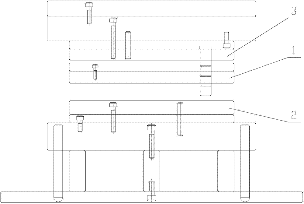
[0020] figure 1 It is a structural schematic diagram of the backplane mold provided by this preferred embodiment. A kind of backboard mould, comprises upper formwork 1, the lower formwork 2 that forms mold cavity with upper formwork 1, and the upper supporting plate 3 that is provided with on upper formwork 1, wherein, set between upper formwork 1 and upper supporting plate 3 There is a buffer element, which can buffer the impact of pressing the template to improve the uniformity of the back plate, and at the same time avoid the problem that the thickness of the back plate changes and cause the mold to be unsuitable. The upper template 1 is connected to the stamping device; the upper template 1 There is an air vent connected with the mold cavity, and an air extraction device is also provided at the air vent; each side of the upper template 1 is provided with a first sealing strip, and each side of the lower template 2 is provided with a The second sealing strip, the first sea...

Embodiment 2

[0024] This preferred embodiment provides a back plate mold, the structure of which is basically the same as that of the preferred embodiment 1. The back plate mold includes an upper template, a lower template forming a mold cavity with the upper template, and an upper supporting plate provided on the upper template , wherein, a buffer element is provided between the upper template and the upper supporting plate, and the upper template is connected with a stamping device; the upper template is provided with a vent hole connected with the mold cavity, and an air extraction device is also provided at the vent hole; the upper template Each side of the lower formwork is provided with a first sealing strip, each side of the lower formwork is provided with a second sealing strip, and the first sealing strip can abut against the second sealing strip to make the mold cavity in a closed state.

[0025] The difference is that the buffer element is not limited to the spring, but can also ...


PUM


Abstract

The invention discloses a back board mold which belongs to the technical fiend of mold. The back board mold is designed to resolve the problems of low producing efficiency and low precision of the prior mold. The back board mold comprises an upper mold, a lower mold and an upper supporting board, wherein the lower mold and the upper mold form a mold cavity, and the upper supporting board is arranged on the upper mold. A buffer element is arranged between the upper mold and the lower mold. The upper mold is connected to a compressing device. The upper mold is equipped with a vent hole which is communicated with the mold cavity. An air dragging device is arranged at the vent hole. Each sides of the upper mold are provided with first sealing trips and each sides of the lower mold are provided with second sealing trips. The first sealing trips contact with the second sealing trips to make the mold cavity to be at enclosed status. The back board mold has the advantages of high production efficiency and high precision, and the rest air in the mold cavity can be removed.

Description

technical field [0001] The invention relates to a back plate mold. Background technique [0002] The backplane is one of the components of the liquid crystal display panel. In the field of display backplane moulds, the existing backplane molds have a relatively simple structure, consisting of an upper mold and a lower mold. When working, after the upper mold and the lower mold are closed, the molten plastic is directly injected into the mold cavity by the injection molding machine to form the final product. This method has many disadvantages. For example, air mixed in the mold cavity due to the lack of a sealing device causes the plastic to be affected by air resistance when flowing in the mold cavity, and the flow is difficult; the air mixed in the mold cavity causes air bubbles in the product, and the product quality declines. ; The production efficiency of the mold is low, the processing precision is low, and the service life is low. Contents of the invention [0003...

Claims


Application Information

Patent Timeline
Patent Type & Authority Applications(China)
IPC IPC(8): B29C45/34
CPCB29C45/34
Inventor 李国新
Owner 昆山电子羽电业制品有限公司
Learn More