Binding devices for steel pipes

A steel pipe and binding belt technology, applied in the field of steel pipe binding devices, can solve the problems of time required for replacement of tightening ropes, increased production costs, and easy dispersal of long strips, and achieves simple structure, extended service life, and clamping operation. Simple and convenient effects

Inactive Publication Date: 2017-04-26
郑惠文
View PDF6 Cites 0 Cited by
  • Summary
  • Abstract
  • Description
  • Claims
  • Application Information

AI Technical Summary

Problems solved by technology

Therefore, there are the following problems in the binding of such steel pipes: on the one hand, because the cutting of the steel pipes is a single operation, the production efficiency is greatly reduced; Tighten them together before they can be bundled. However, these long strips are easy to scatter when tightened together, so the production efficiency is greatly reduced.
[0003] 1) First of all, the tightening rope is used in the device. The tightening rope is placed horizontally on the bottom of the collection frame in advance. After the steel pipe is placed in the collection frame, the motor is started, and the motor drives the transmission mechanism to tighten the tightening rope. Tighten all the steel pipes in the collection frame, in other words, the take-up rope in the collection box is initially cushioned under all the steel pipes, so the weight of all the steel pipes is on the take-up rope, and when the take-up rope starts to tighten At the same time, it needs to move under all the steel pipes, so the driving force of the required motor must be large enough; and the friction force received by the tightening rope during the movement process is large, and the motor is laborious to drive, so the production efficiency is low;
[0004] 2) Under the action of friction, the gravity of the steel pipe and the pulling force of the motor, the tightening rope has friction with the steel pipe and the collection frame. Therefore, the tightening rope is easily worn and broken, and a new tightening rope has to be replaced. Rope, like this, has increased production cost; Simultaneously, it also takes time to replace tightening rope, so also reduced production efficiency;

Method used


Image

  • Binding devices for steel pipes
  • Binding devices for steel pipes
  • Binding devices for steel pipes

Examples


Embodiment Construction

[0032] The present invention will be described in further detail below in conjunction with the accompanying drawings and specific embodiments.

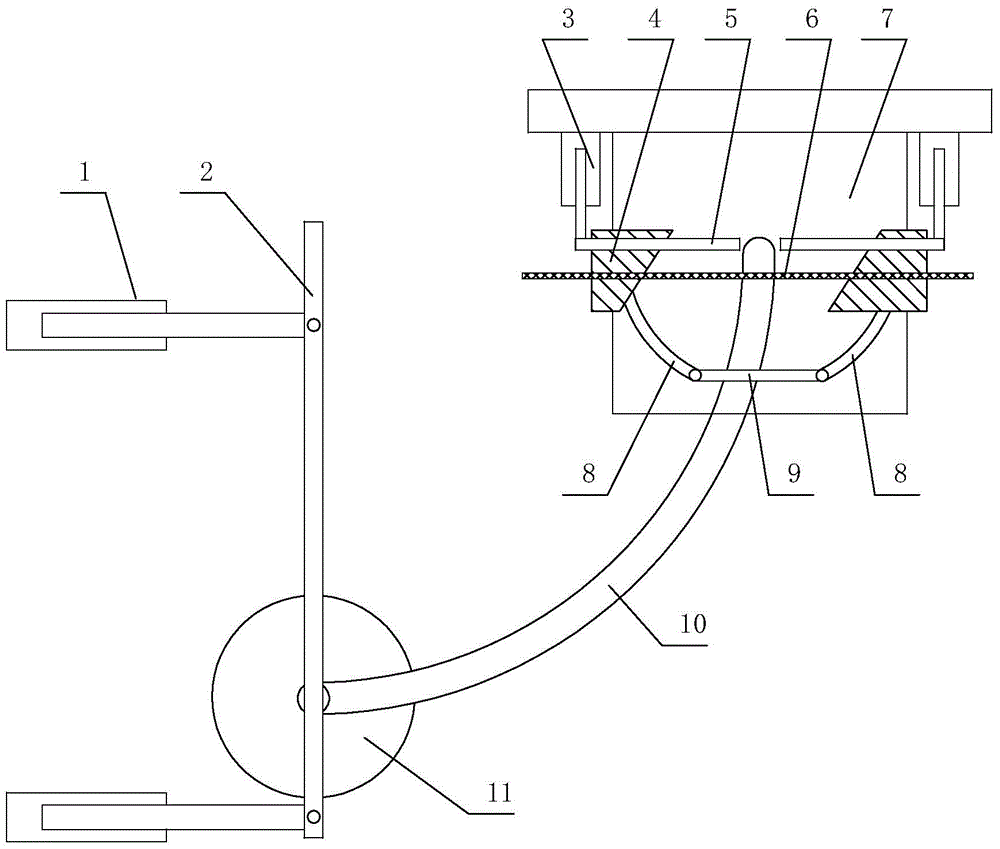
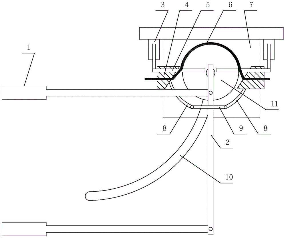
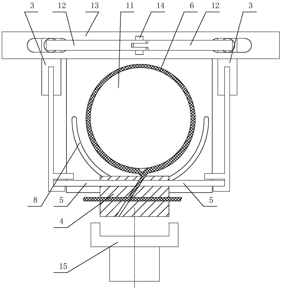
[0033] Depend on Figure 1 to Figure 8 It can be seen from the structural schematic diagram of the binding device of the present invention for steel pipes that it includes a clamping device 11, a conveying device, a binding device and a rope twisting device, the clamping device 11 is slidingly connected with the conveying device, and the binding device passes through The track is connected with the conveying device, and the rope twisting device is disconnected or connected with the binding device. The binding device includes a bottom plate 7, two sets of binding assemblies located on both sides of the steel pipe, and a driving assembly that drives the two sets of binding assemblies to approach or move away from each other at the same time.

[0034]Each group of binding components includes a binding cylinder 3, a binding block 4 and a...


PUM


Abstract

The invention discloses a binding device for a steel pipe. The device comprises a clamping device (11), a conveying device, a binding device and a rope twisting device. The clamping device (11) is in sliding connection with the conveying device, the binding device is connected with the conveying device through a conveying track, and the rope twisting device is disconnected or connected with the binding device. The binding device comprises a base plate (7), two groups of binding assemblies located on two sides of the steel pipe and two groups of driving assemblies used for driving the two groups of binding assemblies to draw close or deviate from each other. By means of the structure, on one hand, the bound steel pipes are still subjected to constraint force, the problem that the steel pipes are loose and roll away is resolved; on the other hand, the bound steel pipes are very stable in a package box and are convenient to transport.

Description

technical field [0001] The invention relates to the technical field of machinery, in particular to a steel pipe binding device for binding and packing a plurality of strip-shaped steel pipes. Background technique [0002] In all walks of life, steel pipes or steel bars are used in various productions, and for steel pipes or steel bars with smaller diameters, manufacturers usually bundle multiple steel pipes to facilitate storage and counting. In the prior art, the binding of such steel pipes is usually to cut the steel pipes into equal-length rods one by one, and then manually bind these rods with the same number. Therefore, there are the following problems in the binding of such steel pipes: on the one hand, because the cutting of the steel pipes is a single operation, the production efficiency is greatly reduced; Tighten them together before they can be bundled. However, these long strips are easy to scatter when they are tightened together, so the production efficiency i...

Claims


Application Information

Patent Timeline
Patent Type & Authority Patents(China)
IPC IPC(8): B65B13/22B65B13/28B65B13/20B65B13/18B65B27/10
CPCB65B13/18B65B13/20B65B13/22B65B13/28B65B27/10
Inventor 郑惠文
Owner 郑惠文
Why Eureka
Try Eureka