
Electromagnetic valve

A solenoid valve and valve body technology, applied in the field of solenoid valves, can solve the problems of increased number of parts and assembly man-hours, cost reduction, difficulties, etc., and achieve the effect of reducing the number of parts and assembly man-hours, cost, and preventing damage

Inactive Publication Date: 2015-08-19
KEIHIN CORP
View PDF5 Cites 2 Cited by
  • Summary
  • Abstract
  • Description
  • Claims
  • Application Information

AI Technical Summary

Problems solved by technology

[0005] However, in order to hold the hub portion of the spool on the second small-diameter shaft portion, the holding member for supporting the hub portion is pressed into the end portion of the second small-diameter shaft portion that is continuously provided than the second small-diameter shaft portion. Since the third small-diameter shaft has a small diameter, the number of parts and assembly man-hours increase, making it difficult to reduce costs

Method used


Image

  • Electromagnetic valve
  • Electromagnetic valve
  • Electromagnetic valve

Examples


Embodiment Construction

[0034] Embodiments of the present invention will be described below based on the drawings.

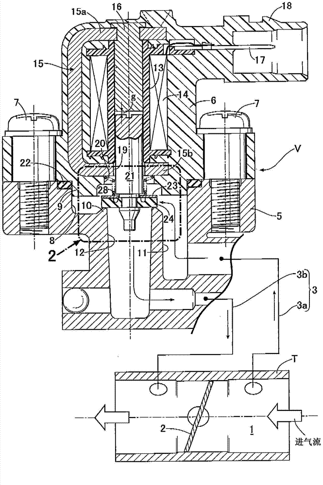
[0035] first in figure 1 Among them, a throttle body T installed on an unillustrated engine has an intake port 1 connected to the intake port of the engine, and a butterfly throttle valve that opens and closes the intake port 1 to control the amount of the intake port of the engine. The 2 shafts are supported on the throttle body T. And a bypass 3 is connected to the throttle body T, and the bypass 3 bypasses the throttle body T to communicate between the upstream and downstream parts of the intake passage 1, and the electromagnetic valve of the present invention is installed in the middle of the bypass 3. valve V. This electromagnetic valve V is a normally closed type, and the bypass 3 can be conducted by opening the valve.

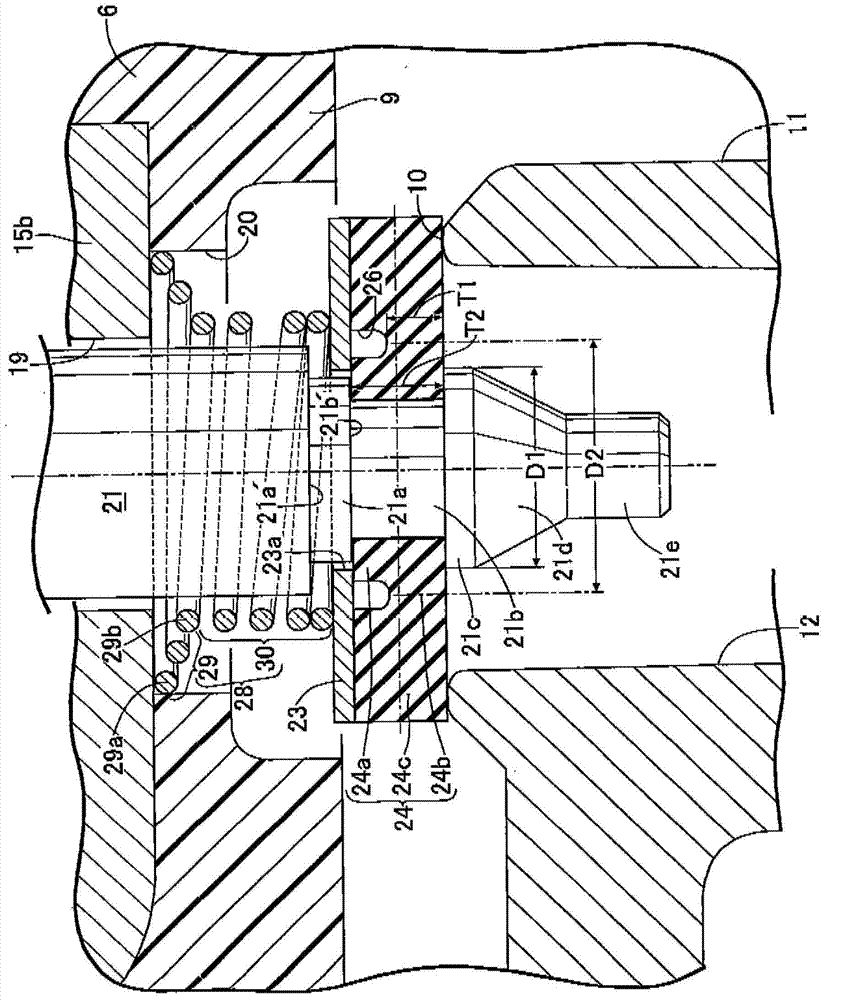
[0036] For the solenoid valve V, use the figure 1 and figure 2 Detailed description.

[0037] The solenoid valve V includes: a valve body 5 supported by t...


PUM


Abstract

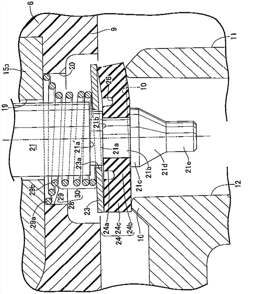
The present invention provides an electromagnetic valve, which can reduce the number of components, shorten the assembly time and reduce the cost. The end portion of a plunger (21) is continuously provided with first minor-diameter shaft portions (21a). The end portions of the first minor-diameter shaft portions (21a) are continuously provided with second minor-diameter shaft portions (21b). A valve core (24) is hermetically embedded and engaged with the shaft bossing parts (24a) of the second minor-diameter shaft portions (21b). A seating part (24c) is arranged on a valve seat (10). A thin-wall bending part (24b) is configured to connect the shaft bossing parts (24a) with the seating part (24c), so that the shaft bossing parts (24a) and the seating part (24c) are capable of moving in a relatively inclined manner. A spring seat plate (23) abuts against the valve core (24) to support the movable end of a valve spring (28). The spring seat plate (23) is in clearance fit with the first minor-diameter shaft portions (21a). The end portions of the second minor-diameter shaft portions (21b) are integrally and continuously provided with flanges (21c) for connecting the shaft bossing parts (24a) onto the second minor-diameter shaft portions (21b). The shaft bossing parts (24a) are good in expanding elasticity so as to be able to pas through the flanges (21c).

Description

technical field [0001] The present invention relates to an improvement of a solenoid valve consisting of a valve body having a valve seat, a solenoid support body joined to the valve body, and a valve body made of an elastic material. The core, the valve core is seated on the valve seat; the plunger supports the valve core and is slidably supported on the solenoid support body; the valve spring is seated on the valve core toward the valve spring. The seat direction of the valve seat exerts force; and a solenoid, which is installed on the solenoid support body, and when energized, overcomes the active force of the valve spring to make the plunger move towards the valve. For the fully open side of the core, a first small-diameter shaft portion connected by a first annular step is continuously provided at the end portion of the plunger on the valve seat side, and at the end portion of the first small-diameter shaft portion The second small-diameter shaft part connected by the se...

Claims


Application Information

Patent Timeline
Patent Type & Authority Applications(China)
IPC IPC(8): F16K31/06F16K1/32
CPCF16K1/32F16K1/36F16K31/06
Inventor 三岛基弘渡部庸三户部雅昭
Owner KEIHIN CORP
Learn More