Testing device for measuring hydrodynamic gap pressure of bottom plates of plunge pool

A test device and hydrodynamic pressure technology, which is applied in the direction of measuring devices, instruments, suspension and porous material analysis, etc., can solve the problems of not considering the influence of gap hydrodynamic pressure, not being able to simulate the deformation of the concrete floor, and being unable to consider it

Inactive Publication Date: 2015-08-19
POWERCHINA ZHONGNAN ENG
View PDF5 Cites 9 Cited by
  • Summary
  • Abstract
  • Description
  • Claims
  • Application Information

AI Technical Summary

Problems solved by technology

[0005] 1. The device designs a test section within the impact area near the impact point of the water tongue in the pool. The test section is arranged with sensors along the transverse direction, which can only analyze the distribution law of the dynamic water pressure in the gap along the horizontal direction, but cannot obtain the distribution of the dynamic water pressure in the gap along the longitudinal direction. In other words, the distribution law of the gap hydrodynamic pressure in the wall jet area upstream and downstream of the impact zone cannot be obtained, while the gap hydrodynamic pressure in the wall jet area is often greater than the surface hydrodynamic pressure, and the floor plate is subjected to a large upward force, which is The main areas of instability and damage in the pad;
[0006] 2. The test section is a reverse-arched arch ring, and the arch ring is not divided into floor plates longitudinally, that is, only transverse joints are set in the upstream and downstream, and no longitudinal joints are set along the direction of water flow. , which is inconsistent with reality;
This device does not consider the influenc

Method used


Image

  • Testing device for measuring hydrodynamic gap pressure of bottom plates of plunge pool
  • Testing device for measuring hydrodynamic gap pressure of bottom plates of plunge pool
  • Testing device for measuring hydrodynamic gap pressure of bottom plates of plunge pool

Examples


Embodiment Construction

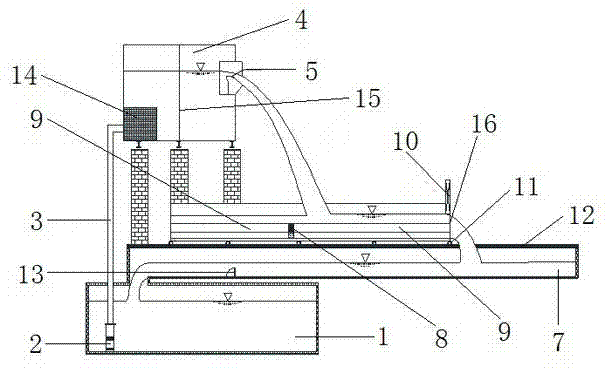
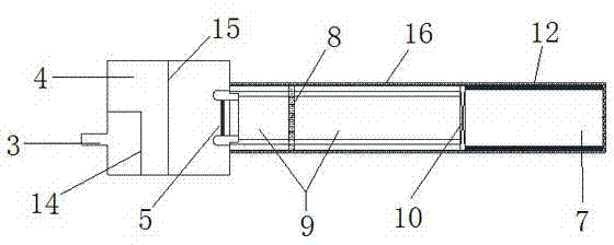
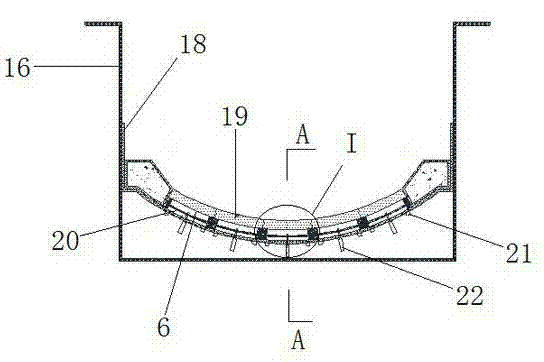
[0038] Such as Figure 1 to Figure 5 As shown, an embodiment of the present invention comprises water cushion pond and five pressure sensors 22, and described water cushion pond comprises casing 16 movable along water flow direction, test section 8 at bottom of casing 16, bottom of casing 16 and Two non-test sections 9 of transverse seams 26 are respectively formed between the upstream and downstream ends of the test section 8, and a liner 18 is provided between the test section 8 and the bottom of the box body 16, and a liner 18 is formed between the liner 18 and the test section 8. The bottom seam 6, the pressure sensor 22 passes through the liner 18 and enters the bottom seam 6, and the five pressure sensors 22 are arranged in the transverse direction. It includes a track 12 arranged along the water flow direction, a pulley 11 is installed at the bottom of the box body 16, and the box body 16 moves on the track 12 through the pulley 11. In order to meet the strength and lo...


PUM


Abstract

The invention discloses a testing device for measuring the hydrodynamic gap pressure of bottom plates of a plunge pool. The testing device comprises the plunge pool and pressure sensors, wherein the plunge pool comprises a box, a testing section and non-testing sections; the box can move along the direction of water flow; the testing section is arranged at the bottom of the box; according to the non-testing section, transverse seams are formed in the bottom of the box and between the upstream and downstream ends of the testing section respectively; a lining plate is arranged between the testing section and the bottom of the box; a bottom seam is formed between the lining plate and the testing section; the pressure sensors pass through the lining plate and enter the bottom seam. According to the testing device, a transverse distribution rule of the hydrodynamic gap pressure can be obtained, and a longitudinal distribution rule of the hydrodynamic gap pressure can also be tested; the influence on the hydrodynamic gap pressure caused by water filled from the transverse seams and longitudinal seams is comprehensively considered; the influence on the hydrodynamic gap pressure caused by different sizes of uplift pressure is considered; the hydrodynamic gap pressure of the transverse seams or the longitudinal seams under different extents of water-seal inactivation can be measured; the deformation of concrete bottom plates can be simulated, and the device more accords with actual engineering.

Description

technical field [0001] The invention belongs to the technical field of water conservancy and hydropower engineering, and in particular relates to a test device for measuring the dynamic water pressure in the gap of the bottom plate of a pond. Background technique [0002] The selection and design of flood discharge and energy dissipation methods under high water head and large flow rate is one of the key technologies in the construction of high dams. Flood water is often released through the openings of the dam body, and water cushion ponds are lined downstream of the dam to dissipate excess kinetic energy and prevent the downstream of the dam from being damaged. Scour to ensure the stability of the riverbed and the slopes on both banks. According to the shape of the cross section, the pad pond can be divided into two types: reverse arch and bottom. [0003] The stability of the pad pond depends on the stability of the bottom plate, and the stability of the bottom plate dep...

Claims


Application Information

Patent Timeline
IPC IPC(8): G01N3/00G01N15/08
Inventor 张春财杜宇王立杰戴晓兵孙建赵燕华樊新建张金明
Owner POWERCHINA ZHONGNAN ENG
Why Eureka
Try Eureka