Optical fiber cutting method and sandpaper cutter

A cutting method and cutting knife technology, applied in the direction of optical waveguide coupling, etc., can solve a lot of manpower, material resources and other problems, and achieve the effect of saving equipment costs and cutting costs of optical fibers

Inactive Publication Date: 2015-08-19
SHANGHAI HONGHUI OPTICS COMM TECH
View PDF4 Cites 0 Cited by
  • Summary
  • Abstract
  • Description
  • Claims
  • Application Information

AI Technical Summary

Problems solved by technology

For production and processing enterprises, this method needs to be equipped with a large number of optical fiber cutting knives, and the daily maintenance of the blades requires a lot of manpower and material resources.

Method used


Image

  • Optical fiber cutting method and sandpaper cutter
  • Optical fiber cutting method and sandpaper cutter
  • Optical fiber cutting method and sandpaper cutter

Examples


Embodiment Construction

[0017] The present invention will be further described below in conjunction with accompanying drawing.

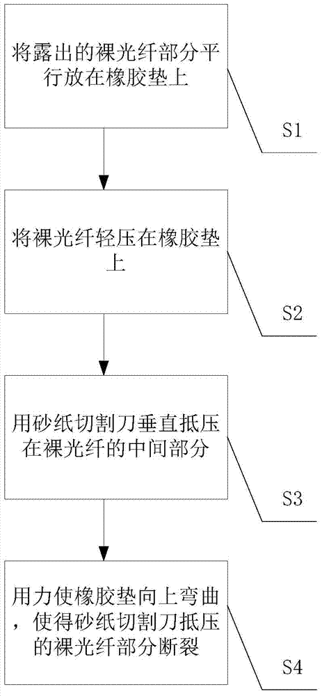
[0018] see figure 1 , one of the optical fiber cutting method of the present invention, comprises the following steps:

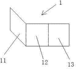
[0019] Step S1, placing the exposed bare optical fiber part parallel on the rubber pad, so that both sides of the bare optical fiber and the rubber pad are parallel to each other. In this embodiment, the hardness of the rubber pad is 70 degrees, and the size is 60mm*20mm*4mm.

[0020] Step S2, lightly press the bare optical fiber on the rubber pad with the thumb of the left hand, and press the index finger and middle finger against the bottom of the rubber pad.

[0021] In step S3, the middle part of the bare optical fiber is selected, and the right hand is gently cut vertically with a sandpaper cutter, so as to press against the middle part of the bare optical fiber.

[0022] In step S4, the right hand presses the other side of the bare optical fiber ...


PUM


Abstract

The present invention discloses an optical fiber cutting method which comprises a step of pressing a bare optical fiber on a rubber pad to be parallel with two sides of the rubber pad, a step of allowing a sandpaper cutter to vertically press the middle part of the bare optical fiber, and a step of allowing the rubber pad to bend upward by using force such that a part of the bare optical fiber pressed by the sandpaper cutter is broken. The operation is easy, the sandpaper cutter, an optical fiber cutter is not needed, and the daily maintenance of a blade is not needed. The invention also discloses the sandpaper cutter which comprises an 88mm*30mm waterproof abrasive paper and a tape. The waterproof abrasive paper is divided into a 30mm*30mm first area, a 30mm*30mm second area and a 28mm*30mm third area from left to right. The abrasive surface of the first area is outward folded to cover the second area, and the abrasive surface of the third area is outward folded to cover the first area. The overlapped three areas are bonded together by the tape, and the two sides with sands are used as the blades of the cutter.

Description

technical field [0001] The invention relates to the field of optical fiber cutting, in particular to an optical fiber cutting method and a cutting knife used therefor. Background technique [0002] At present, the method used for optical fiber fusion in the industry: use fiber strippers to strip off the coating layers of the two optical fibers by 40-50mm respectively, wipe them clean, put them in an optical fiber cutter for cutting, and perform fusion splicing after cutting. For production and processing enterprises, this method needs to be equipped with a large number of optical fiber cutting knives, and the daily maintenance of the blades requires a lot of manpower and material resources. Contents of the invention [0003] The purpose of the present invention is to provide an optical fiber cutting method, which is simple and easy to operate, uses a sandpaper cutting knife, does not need to be equipped with an optical fiber cutting knife, and does not need to perform dail...

Claims


Application Information

Patent Timeline
Patent Type & Authority Applications(China)
IPC IPC(8): G02B6/25
CPCG02B6/25
Inventor 黄惠良赵继鸿王坤陈子勇
Owner SHANGHAI HONGHUI OPTICS COMM TECH
Why Eureka
Try Eureka