Solar silicon wafer wire cutting guide roller and manufacturing method and special film coating machine and electroplating machine

A solar silicon wafer and wire cutting technology, applied in circuits, electrolytic coatings, photovoltaic power generation, etc., can solve the problems of increasing labor intensity of workers, unstable slice quality, waste of equipment resources, etc., to improve equipment utilization and prevent fluctuation trends and wear-resistant effect, the effect of reducing line marks

Inactive Publication Date: 2011-10-26
蒙特集团(香港)有限公司
View PDF4 Cites 9 Cited by
  • Summary
  • Abstract
  • Description
  • Claims
  • Application Information

AI Technical Summary

Problems solved by technology

[0004] With the development of the entire solar energy industry, composite polyurethane elastomer guide rollers are widely used in solar silicon wafer wire cutting. Because the wear resistance of its surface is affected by the material structure of the polymer, the actual service life cycle is between 150-200 hours. Unstable slice quality has been caused
Replacing guide rollers during the production process is a very complicated job, and it takes 5-8 hours for professional operators to replace them, which also means that the company needs to stop for 5-8 hours, resulting in waste of other machine equipment resources. It also needs to clean other equipment, and the surface repair will increase the cost of the enterprise and increase the labor intensity of the workers. The whole industry is working on how to improve the surface wear resistance and service life of the V-shaped steel wire guide roller, improve the utilization rate of the machine, and reduce the cutting cost. Find a new way without changing the manufacturing process of the existing cutting guide roller

Method used


Image

  • Solar silicon wafer wire cutting guide roller and manufacturing method and special film coating machine and electroplating machine
  • Solar silicon wafer wire cutting guide roller and manufacturing method and special film coating machine and electroplating machine
  • Solar silicon wafer wire cutting guide roller and manufacturing method and special film coating machine and electroplating machine

Examples


Embodiment Construction

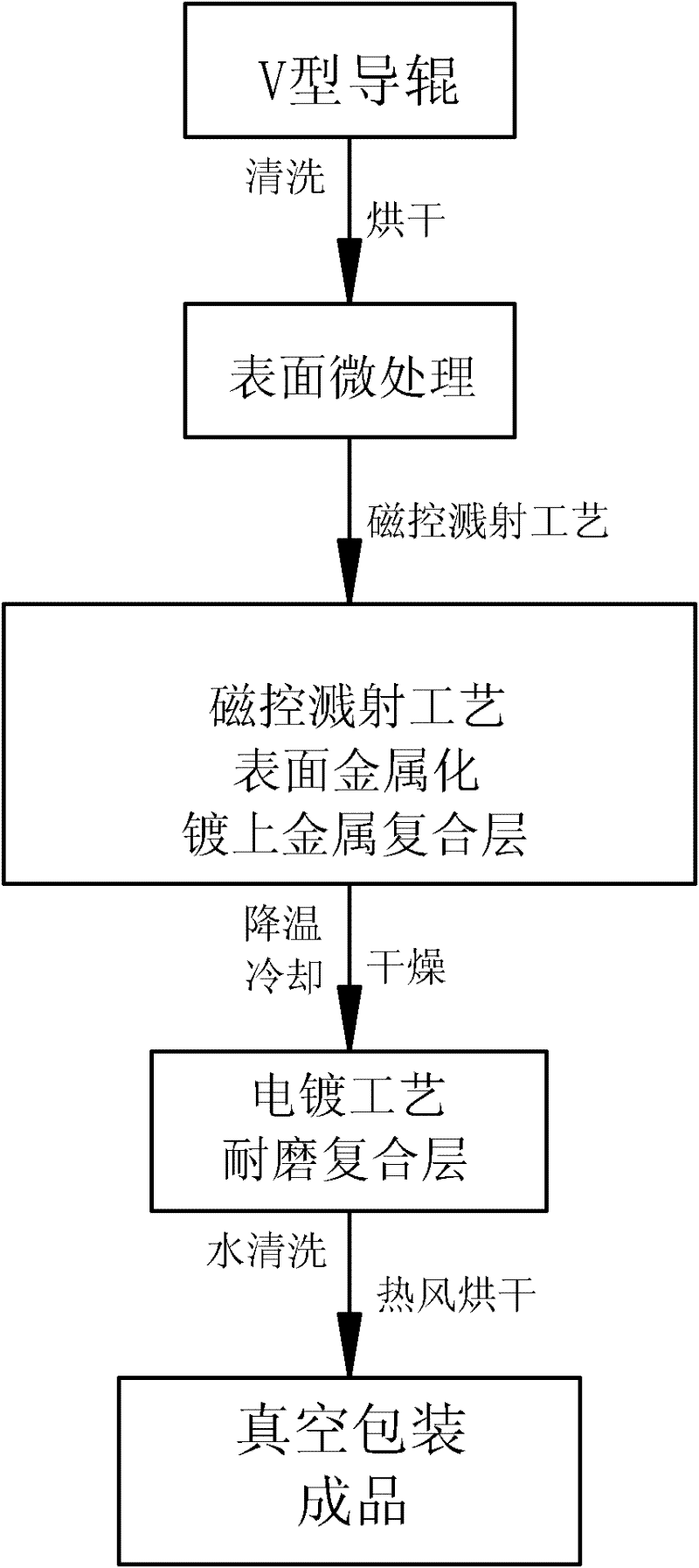
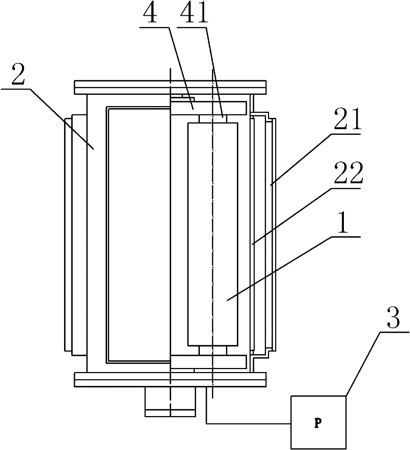
[0041] The present invention is described in further detail now in conjunction with accompanying drawing. These drawings are all simplified schematic diagrams, which only illustrate the basic structure of the present invention in a schematic manner, so they only show the configurations related to the present invention.

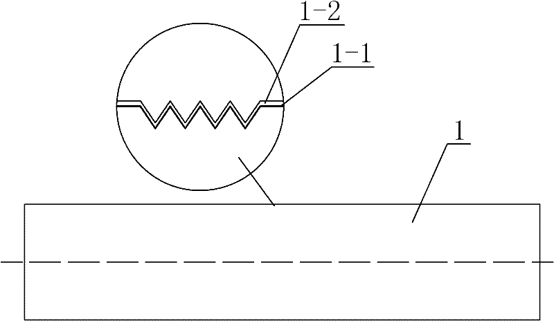
[0042] Such as figure 1The best embodiment of the shown solar silicon wafer wire cutting guide roller of the present invention has the V-shaped guide roller base 1 made of composite polyurethane, and the V-shaped guide roller base 1 is coated with a metal composite layer 1-1 on the surface. The surface of the metal composite layer 1-1 is coated with a wear-resistant composite layer 1-2, the metal composite layer 1-1 is a metal composite layer composed of one or more of nickel, titanium, copper and chromium, and the wear-resistant composite layer 1- 2 is an anti-adhesive polymer, and the anti-adhesive polymer is mixed with wear-resistant particles. The thickn...


PUM

PropertyMeasurementUnit
particle diameteraaaaaaaaaa

Abstract

The invention relates to a solar silicon wafer wire cutting guide roller and a manufacturing method and a special film coating machine and an electroplating machine. the method comprises the following steps of: making a V-shaped guide roller base body made from composite polyurethane, plating a metal composite layer on the surface of the V-shaped guide roller base body, and plating a wear-resistant composite layer on the surface of the metal composite layer,wherein the metal composite layer is compounded by one or more then one of nickel, titanium, copper and chromium, the wear-resistant composite layer is a antiseize polymer in which wear-resistant particles are contained. According to the invention, under the condition of not changing the existing cutting technique, the service life of the V-shaped guide roller manufactured by the invention is prolonged, the replacement frequency can be reduced, the cutting yield is stabilized, the equipment utilization ratio is improved, and the overall cutting cost is lowered.

Description

technical field [0001] The invention relates to the technical field of solar silicon wafer cutting equipment, in particular to a solar silicon wafer wire cutting guide roller, a manufacturing method, a special coating machine and an electroplating machine. Background technique [0002] China's photovoltaic power generation industry has developed rapidly in the past five years, and the investment in solar silicon wafer cutting equipment has been put into operation by dozens of times in recent years. Among them, the V-shaped wire rollers used for cutting steel wires are consumed in large quantities with the expansion of the slicer. , Among them, the surface wear and wear resistance characteristics of the V-shaped wire roller directly affect the quality of the slice, the utilization rate of the equipment and the comprehensive wire cutting cost. [0003] In the process of wire cutting of solar silicon wafers, the whole mechanism is to use the hard characteristics and sharp water...

Claims


Application Information

Patent Timeline
Patent Type & Authority Applications(China)
IPC IPC(8): B28D7/00B28D5/04C23C14/35C23C14/20C25D15/00C25D9/02
CPCH01L31/0508H01L31/0547H01L31/18Y02E10/52Y02P70/50
Inventor 励征
Owner 蒙特集团(香港)有限公司
Why Eureka
Try Eureka