Flash lamp control method and terminal

A control method and flashlight technology, which are applied to TVs, color TV parts, electrical components, etc., can solve the problems of affecting shooting effects, overexposure of scenes, underexposure of scenes, etc.

Active Publication Date: 2015-08-19
GUANGDONG OPPO MOBILE TELECOMM CORP LTD
View PDF6 Cites 23 Cited by
  • Summary
  • Abstract
  • Description
  • Claims
  • Application Information

AI Technical Summary

Problems solved by technology

However, in practice, it has been found that the brightness and darkness of the scenes shown in the camera will vary during shooting. Some of the scenes may be under strong light, while others are under low light. At this time, when using the same flash for supplementary light, It is easy to cause problems such as overexposure of some scenes, or underexposure of some scenes, which will reduce the quality of the photos taken and seriously affect the shooting effect

Method used


Image

  • Flash lamp control method and terminal
  • Flash lamp control method and terminal
  • Flash lamp control method and terminal

Examples


Embodiment Construction

[0020] The following will clearly and completely describe the technical solutions in the embodiments of the present invention with reference to the accompanying drawings in the embodiments of the present invention. Obviously, the described embodiments are some of the embodiments of the present invention, but not all of them. Based on the embodiments of the present invention, all other embodiments obtained by persons of ordinary skill in the art without making creative efforts belong to the protection scope of the present invention.

[0021] Embodiments of the present invention provide a flashlight control method and a terminal, which can improve the shooting effect during shooting and effectively improve the user's shooting experience. Each will be described in detail below.

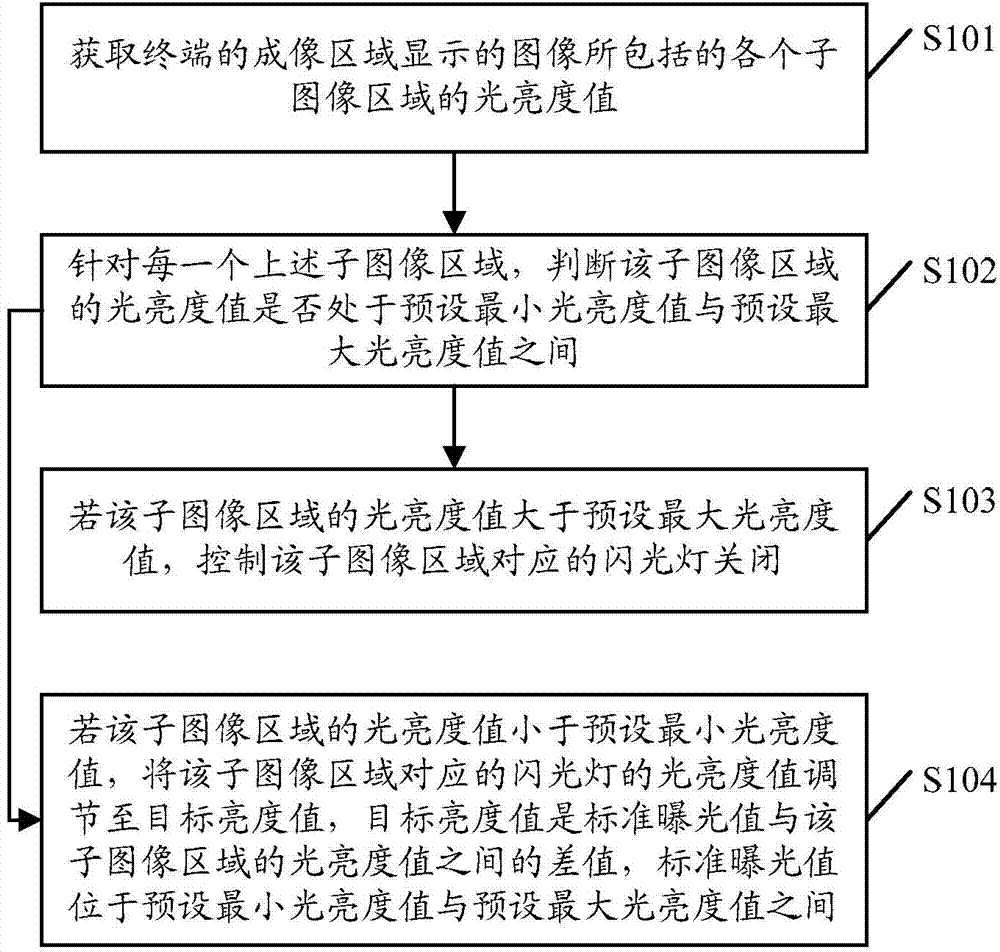
[0022] see figure 1 , figure 1 It is a schematic flowchart of a flash control method provided by an embodiment of the present invention. Such as figure 1 As shown, the flash control method may includ...


PUM


Abstract

The embodiment of the present invention discloses a flash lamp control method and a terminal. The method comprises the steps of acquiring light luminance values in all sub-image regions contained in an image displayed in the imaging region of the terminal; for each sub-image region, judging whether the acquired light luminance value of the sub-image region is within the range from a preset minimum luminance value to a preset maximum luminance value or not; on the premise that the acquired light luminance value of the sub-image region is larger than the preset maximum luminance value, controlling a flash lamp corresponding to the above sub-image region to be switched off, wherein the sub-image regions and flash lamps are in one-to-one correspondence manner; on the premise that the acquired light luminance value of the sub-image region is smaller than the preset minimum luminance value, regulating the light luminance value of the flash lamp corresponding to the above sub-image region to be a target luminance value, wherein the target luminance value is the difference value between a standard exposure value and the light luminance value of the sub-image region, and the standard exposure value is between the preset minimum luminance value and the preset maximum luminance value. According to the embodiments of the invention, the shooting effect of the terminal is improved during the shooting process. Meanwhile, the shooting experience of users is effectively improved.

Description

technical field [0001] The present invention relates to the technical field of terminals, in particular to a flashlight control method and a terminal. Background technique [0002] With the rapid development of terminal technology, there are more and more mobile terminals with a shooting function, such as digital cameras, mobile phones, and tablet computers. In addition, most of the mobile terminals capable of photographing are equipped with a camera as well as a flashlight, which can improve the quality of photos taken in low-light environments. However, in practice, it has been found that the brightness and darkness of the scenes shown in the camera will vary during shooting. Some of the scenes may be under strong light, while others are under low light. At this time, when using the same flash for supplementary light, It is easy to cause problems such as over-exposure of some scenes, or under-exposure of some scenes, so that the quality of the captured photos is reduced, ...

Claims


Application Information

Patent Timeline
Patent Type & Authority Applications(China)
IPC IPC(8): H04N5/235
CPCH04N23/70H04N23/75
Inventor 张强
Owner GUANGDONG OPPO MOBILE TELECOMM CORP LTD
Why Eureka
Try Eureka