Semi-spade rudder cavitation probability reducing device

A technology of hanging rudder and cavitation, which is applied in the direction of steering with rudder, can solve the problems of increasing the difficulty of shipyard construction, prolonging the design and construction period, and the collision between the rudder blade and the rudder arm, so as to increase the burden and improve the rudder. effective, simple structure

Inactive Publication Date: 2015-08-26
SHANGHAI MERCHANT SHIP DESIGN & RES INST
View PDF7 Cites 1 Cited by
  • Summary
  • Abstract
  • Description
  • Claims
  • Application Information

AI Technical Summary

Problems solved by technology

[0011] 1) Due to the requirements of rudder turning and construction, there needs to be a certain gap between the rudder blade and the rudder arm. If the gap is too small, it will easily cause the rudder blade and the rudder arm to collide when turning the rudder, and bring severe construction precision control to the shipyard. challenge;
[0012] 2) The design of the twisted rudder requires a lot of calculations, which will greatly increase the difficulty of shipyard construction and prolong the design and construction period;
[0013] 3) The turbulence device can reduce the corrosion of the cavitation on the rudder blade, but at the same time it also increases the resistance and affects the economy of the ship;
[0015] 5) The use of fully suspended rudders or other high-performance rudders will greatly increase the cost of the shipyard

Method used


Image

  • Semi-spade rudder cavitation probability reducing device
  • Semi-spade rudder cavitation probability reducing device
  • Semi-spade rudder cavitation probability reducing device

Examples


Embodiment Construction

[0046] The present invention will be further described below in conjunction with specific embodiments and accompanying drawings.

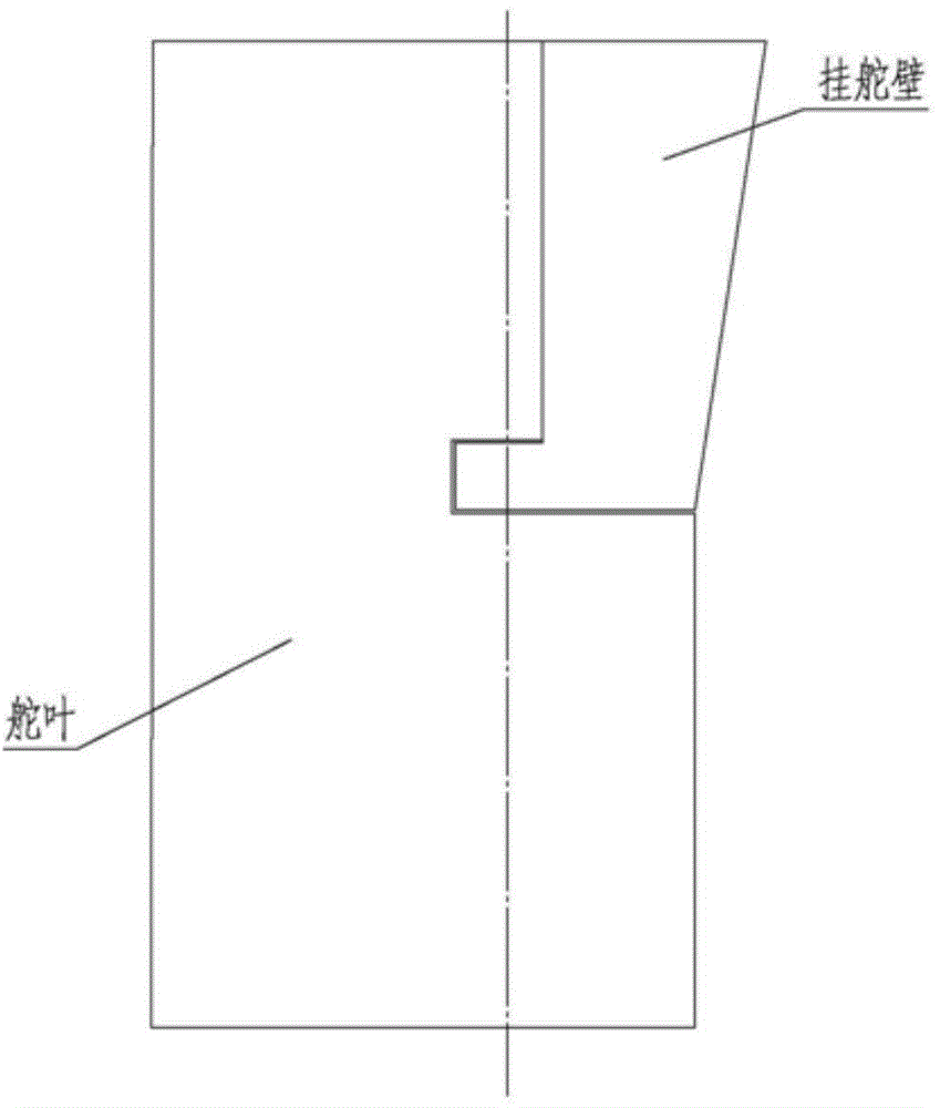
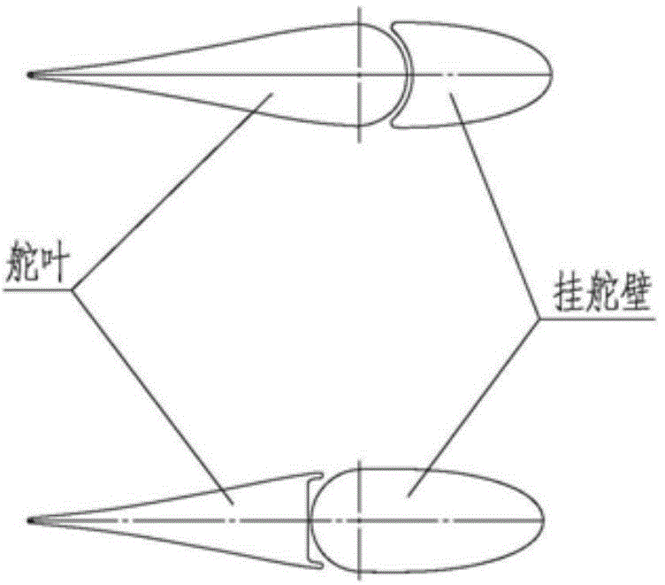
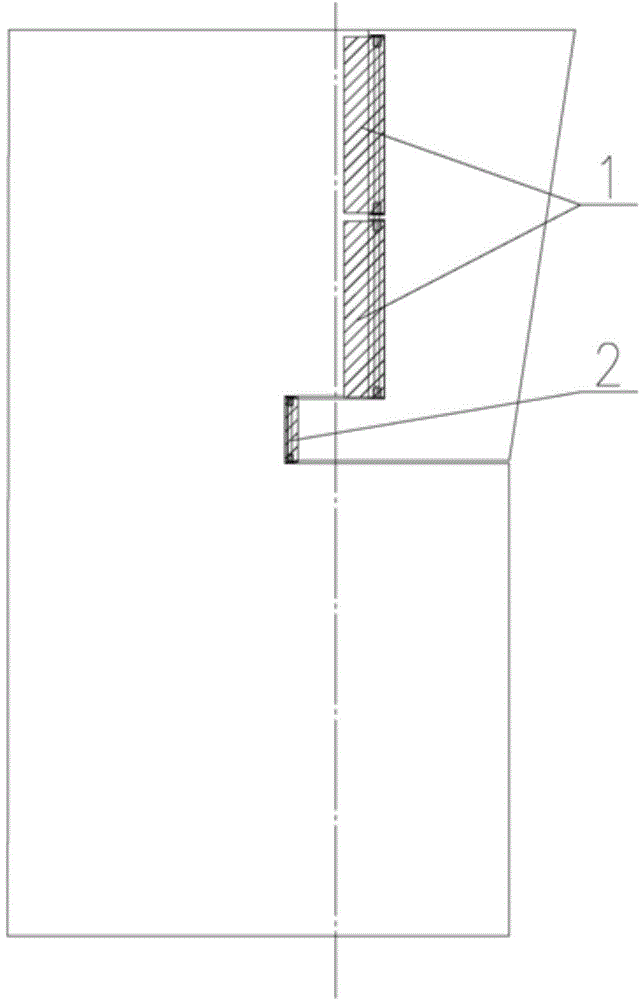
[0047] The device for reducing the cavitation phenomenon of the semi-suspended rudder is divided into two forms, one is the upper deflector 1 with a rotatable fixed shaft at the rudder arm, and the other is a rotatable lower deflector with a fixed shaft at the rudder pin 2, such as image 3 shown. The upper deflector 1 is installed on the rudder arm, and an appropriate number of deflectors 1 can be selected according to the size of the rudder blade; the lower deflector 2 is installed on the rudder blade.

[0048] like Figure 4 As shown, the upper deflector 1 is mainly composed of a fixed shaft 3, an upper bushing 4, an upper bushing 5, a lower bushing 6, a lower bushing 7 and a rubber deflector 8. The fixed shaft 3, the upper bushing 4 and the lower bushing 6 are fixed on the rudder arm; the upper bushing 5, the lower bushing 7 and the rubber d...


PUM


Abstract

The invention relates to a semi-spade rudder cavitation probability reducing device. The semi-spade rudder cavitation probability reducing device comprises at least two upper flow guiding devices fixed on upper part positions of a spade rudder arm and at least two lower flow guiding devices fixed on lower part positions of a rudder blade, wherein an upper rubber flow guiding piece of a luffing side board rotates to a certain angle around a fixing shaft under the effect of the rudder blade and is close to the rudder blade during luffing a semi-spade rudder, the upper rubber flow guiding piece on the other side is close to the rudder blade under the effect of incoming flow, the surfaces of the flow guiding pieces and the rudder blade are in smooth transition, so that turbulent flow and cavitation phenomena are avoided, and the upper rubber flow guiding pieces of a left board and a right board are automatically close to the rudder blade under the effect of the incoming flow when a rudder angle is recovered to 0 degree; upper spring devices and lower spring devices are arranged between shaft sleeves corresponding to the lower flow guiding devices and lining sleeves corresponding to the lower flow guiding devices, the upper spring devices are used for limiting the clockwise rotation of lower rubber flow guiding pieces, the lower spring devices are used for limiting the anticlockwise rotation of the lower rubber flow guiding pieces, and under the effects of the upper spring devices and the lower spring devices, the lower rubber flow guiding pieces invariably have trends of recovering to initial positions and are close to the spade rudder arm.

Description

technical field [0001] The invention relates to a device for reducing the cavitation phenomenon of a semi-suspended rudder, belonging to the technical field of semi-suspended rudder design. Background technique [0002] Due to the mature design and construction technology, semi-suspended rudders are widely used in various types of ships such as bulk carriers, oil tankers, container ships, and ro-ro ships. The semi-suspended rudder is mainly composed of a rudder arm and a rudder blade. There is a gap between the two. The rudder arm is fixed on the hull, and the rudder blade can rotate around the rudder stock. When the semi-suspended rudder is applied to high-speed ships such as container ships, ro-ro ships, and ro-ro passenger ships, the gap between the rudder blade and the rudder arm greatly increases the possibility of rudder blade cavitation. The cavitation phenomenon directly affects the hydrodynamic performance of the rudder blade, and will cause serious corrosion to th...

Claims


Application Information

Patent Timeline
Patent Type & Authority Applications(China)
IPC IPC(8): B63H25/38
Inventor 莫继华赵东国夏玉涛徐蓉高俊
Owner SHANGHAI MERCHANT SHIP DESIGN & RES INST
Why Eureka
Try Eureka