Apparatus and system for enhancing aftertreatment regeneration

a technology of aftertreatment and apparatus, which is applied in the direction of mechanical apparatus, machines/engines, and non-fuel substance addition to fuel, can solve the problems of affecting the regeneration effect of aftertreatment, the need for a post-injection capable fuel system that may be more expensive than desired, and the difficulty of injecting in the cylinder, so as to improve the mixing of injected fuel and exhaust gas, enhance aftertreatment regeneration, and improve the effect of turbulence and shear

Active Publication Date: 2010-09-21
CUMMINS INC
View PDF16 Cites 11 Cited by
  • Summary
  • Abstract
  • Description
  • Claims
  • Application Information

AI Technical Summary

Benefits of technology

[0011]From the foregoing discussion, applicant asserts that a need exists for a system and apparatus to enhance aftertreatment regeneration. Beneficially, such a system and apparatus would allow placement of a fuel injector within an exhaust manifold providing a higher temperature environment, with greater turbulence and shear causing better mixing of injected fuel and exhaust gas. In a further beneficial improvement, the system and apparatus would allow for the continued normal use of EGR, while injecting fuel, compared to in-cylinder dosing. Additionally, the system and apparatus would provide a longer residence time for injected fuel compared to present methods of downstream dosing.
[0015]A system is disclosed to enhance aftertreatment regeneration. The system comprises an internal combustion engine producing an exhaust stream and an exhaust manifold coupled to the engine to receive the exhaust stream. The system further comprises the apparatus coupled to the exhaust manifold and configured to inject fuel into the exhaust stream. The system may further comprise a turbocharger including a turbine inlet port receiving the exhaust stream from the exhaust manifold.

Problems solved by technology

The placement of the fuel injector is a challenge in aftertreatment system design.
However, some of the challenges of in-cylinder dosing include diluting the engine oil with fuel, fuel recycling through the EGR, and the necessity of including a post-injection capable fuel system that may be more expensive than desired (e.g. a common rail fuel system).
Even if the fuel injector temperature limitations are overcome—perhaps through exotic materials and expensive cooling packages—placing the fuel injector into the exhaust manifold, or injecting in-cylinder, is difficult on engines with EGR.
Fuel injected can be recirculated through the EGR path, potentially fouling an EGR cooler and EGR valve, and disrupting the designed torque and operation of the engine.
This results in increased emissions and / or lower power density of the engine.
Placement of the aftertreatment fuel injector downstream of the turbocharger presently causes performance limitations on the aftertreatment system.
Also, in the environment downstream of the turbocharger, the fuel does not experience enough time at temperature to begin breaking down from large hydrocarbon chains to small hydrocarbon chains, further reducing the oxidizing effectiveness of the DOC or other aftertreatment component.

Method used


Image

  • Apparatus and system for enhancing aftertreatment regeneration
  • Apparatus and system for enhancing aftertreatment regeneration
  • Apparatus and system for enhancing aftertreatment regeneration

Examples


Embodiment Construction

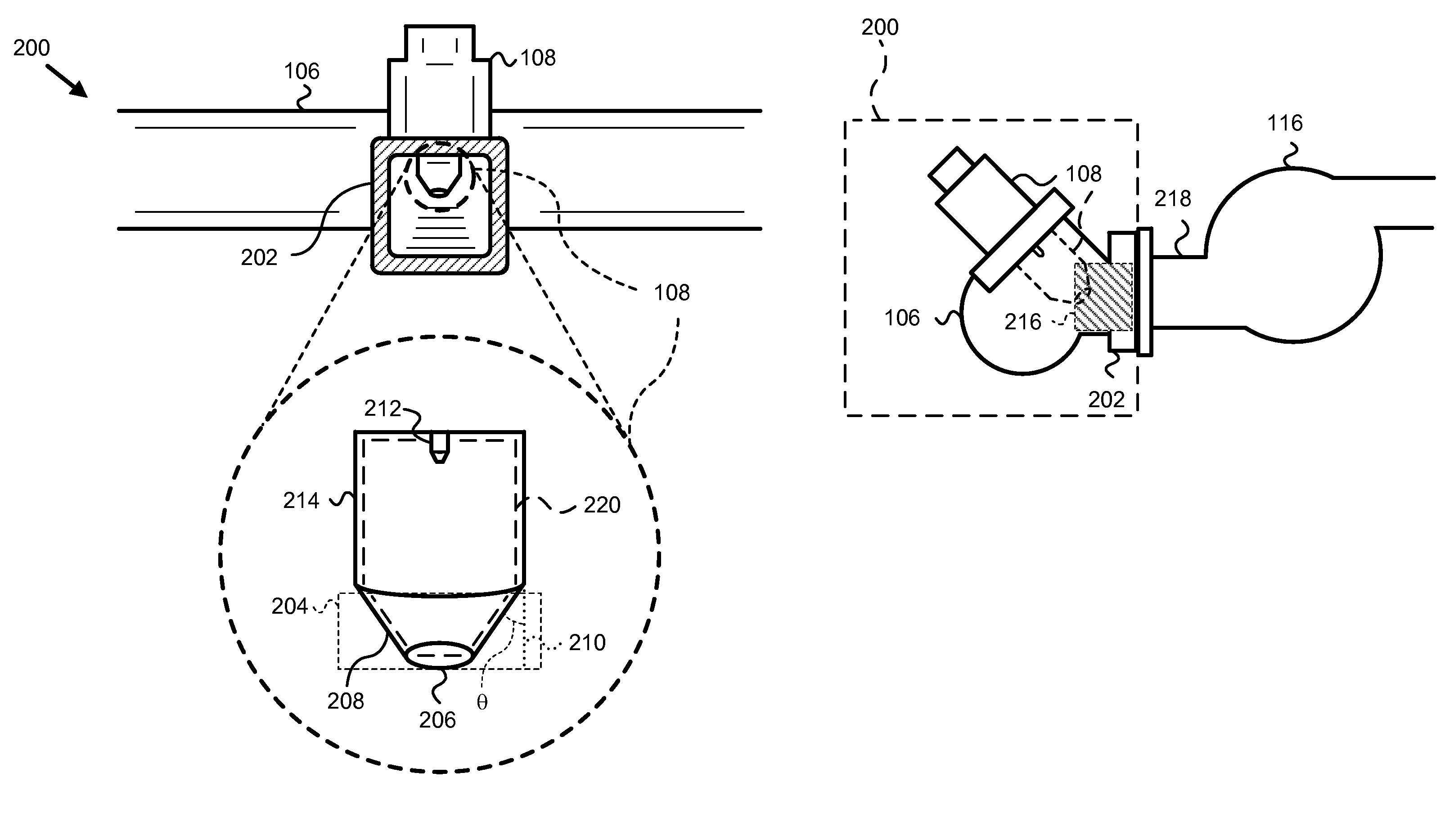
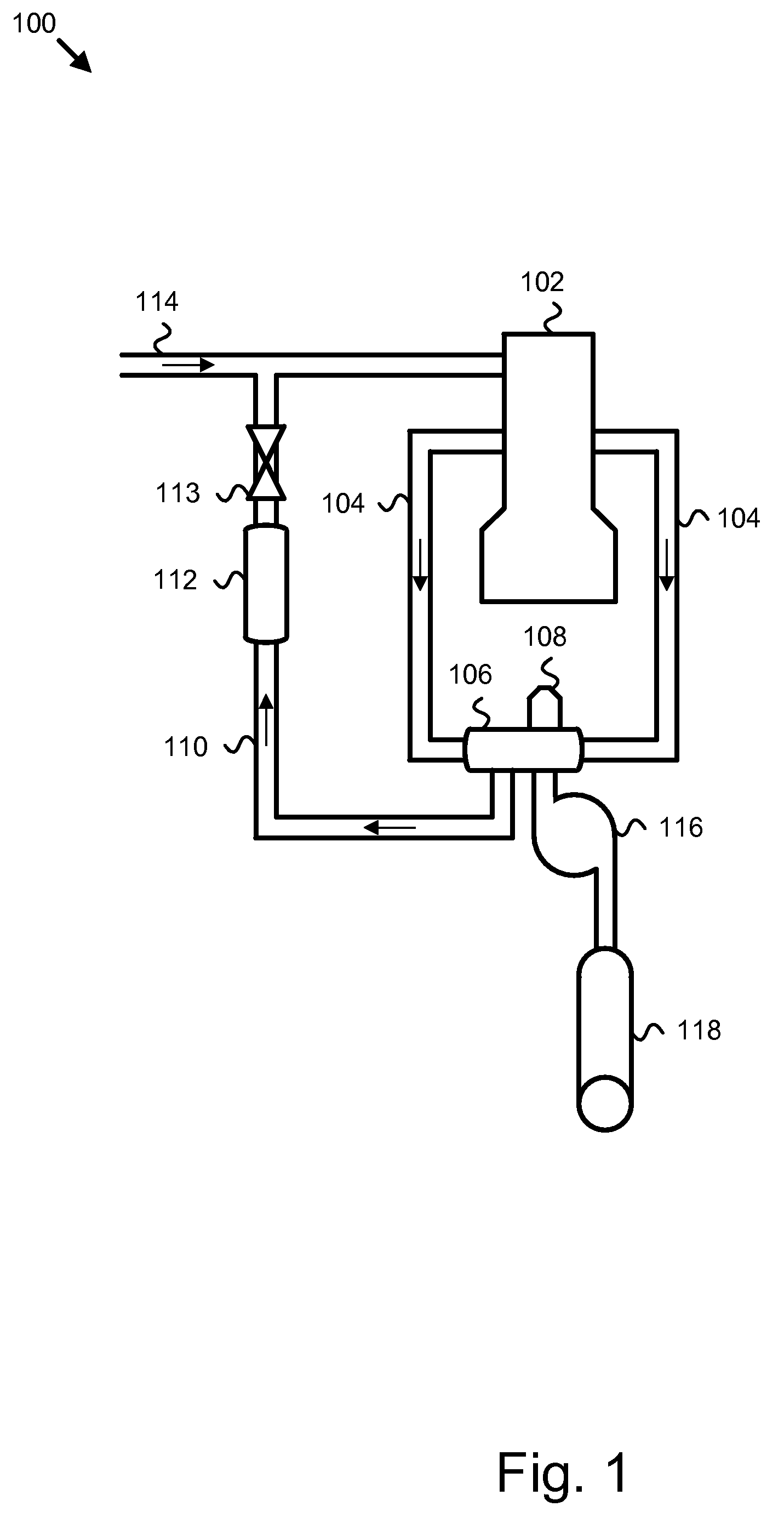
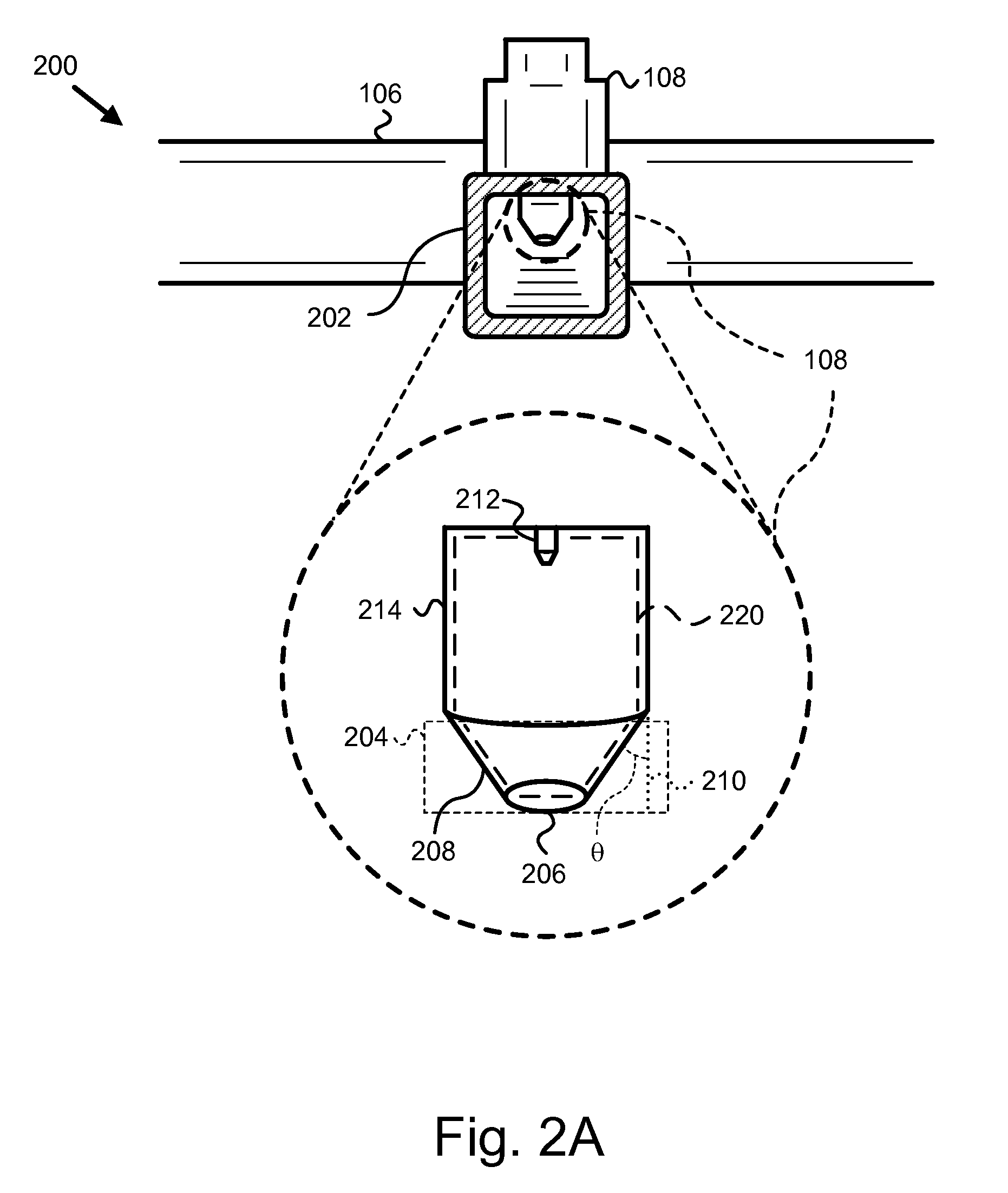
[0025]It will be readily understood that the components of the present invention, as generally described and illustrated in the figures herein, may be arranged and designed in a wide variety of different configurations. Thus, the following more detailed description of the embodiments of the apparatus and system of the present invention, as presented in FIGS. 1 through 4, is not intended to limit the scope of the invention, as claimed, but is merely representative of selected embodiments of the invention.

[0026]Reference throughout this specification to “one embodiment” or “an embodiment” means that a particular feature, structure, or characteristic described in connection with the embodiment is included in at least one embodiment of the present invention. Thus, appearances of the phrases “in one embodiment” or “in an embodiment” in various places throughout this specification are not necessarily all referring to the same embodiment.

[0027]Furthermore, the described features, structure...


PUM


Abstract

An apparatus and system are disclosed for enhancing aftertreatment regeneration. The system includes an internal combustion engine and an exhaust manifold directing the engine exhaust to an aftertreatment system. The system may further include an exhaust gas recycle system and a turbocharger. The system further includes a fuel injector mounted on the exhaust manifold that provides fuel to assist in regenerating an aftertreatment component. The fuel injector is mounted in an apparatus also including a flow dampener, an extender, and a residence chamber. The apparatus allows the fuel to be injected in a high temperature location where it will experience residence time at temperature, and experience shear forces passing through the turbocharger. The extender allows the fuel to be injected at a place in the exhaust manifold where recycling of injected fuel into the engine is minimized.

Description

BACKGROUND OF THE INVENTION[0001]1. Field of the Invention[0002]This invention relates to exhaust gas aftertreatment systems and more particularly to an apparatus and system for enhancing aftertreatment regeneration.[0003]2. Description of the Related Art[0004]Environmental concerns motivate emissions requirements for internal combustion engines throughout much of the world. Governmental agencies, such as the Environmental Protection Agency (EPA) in the United States, carefully monitor the emission quality of engines and set acceptable emission standards, to which all engines must comply. Generally, emission requirements vary according to engine type. Emission tests for compression-ignition (diesel) engines typically monitor the release of diesel particulate matter (PM), nitrogen oxides (NOx), and unburned hydrocarbons (UHC).[0005]The need to comply with emissions requirements encourages the development of exhaust gas aftertreatment systems. Aftertreatment systems frequently include...

Claims


Application Information

Patent Timeline
Patent Type & Authority Patents(United States)
IPC IPC(8): F01N3/00F01N3/10
CPCF01N3/0253F02M25/0718F02M25/0726F01N2610/03F01N2610/08F01N2610/10F02B37/00F02B37/20F02B47/08Y02T10/121F02M26/15F02M26/22
Inventor HERRICK, BRETTMITCHELL, STEPHEN L.
Owner CUMMINS INC
Why Eureka
Try Eureka