Plate heat exchanger

A heat exchanger, laminated technology, applied in the field of laminated heat exchanger, can solve the problems of high manufacturing cost and complex structure, etc.

Inactive Publication Date: 2008-01-09
BEHR GMBH & CO KG
View PDF1 Cites 8 Cited by
  • Summary
  • Abstract
  • Description
  • Claims
  • Application Information

AI Technical Summary

Problems solved by technology

This disclosed plate heat exchanger comprises many parts and is complex in structure
In addition, the manufacturing cost of this known heat exchanger is relatively high

Method used


Image

  • Plate heat exchanger
  • Plate heat exchanger

Examples


Embodiment Construction

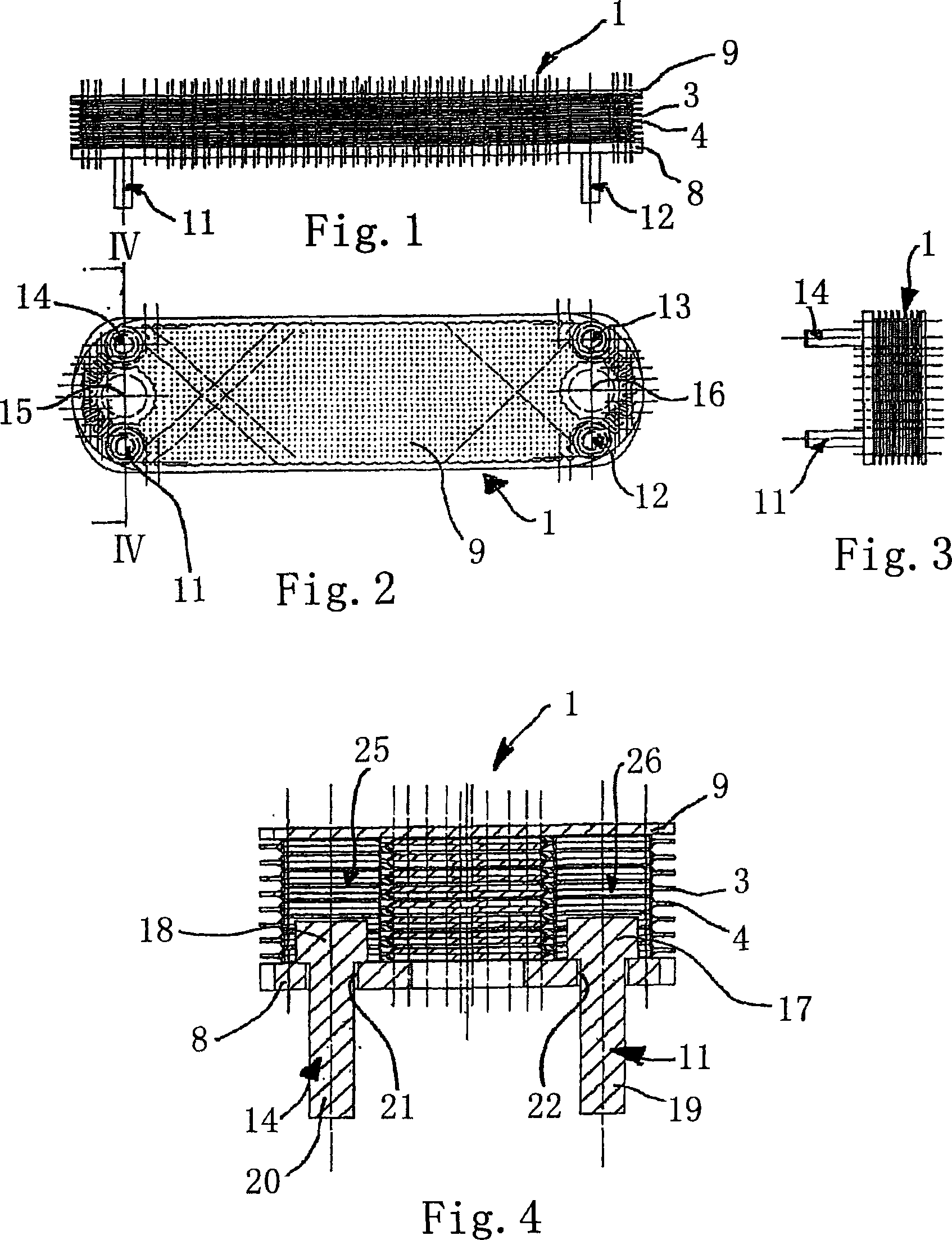
[0027] Fig. 1 is a front view of a laminated heat exchanger 1 according to the present invention. The laminated heat exchanger 1 comprises a plurality of substantially sheet-shaped flat tubes 3 , 4 which are placed one above the other between a base plate 8 and a cover plate 9 . The flat tubes 3 , 4 each have an opening at the end through which the medium to be cooled, in particular engine oil, can flow in or out. The medium to be cooled flows through the flat tubes 3 , 4 in the longitudinal direction. The flat tubes 3 , 4 are impinged on the outside by a cooling fluid which flows around the flat tubes 3 , 4 in a direction perpendicular to the plane of illustration in FIG. 1 .

[0028] FIG. 2 is a plan view of the laminated heat exchanger 1 shown in FIG. 1 . The laminated heat exchanger 1 can be fastened by four screws 11 to 14 to the engine block (not shown) of the motor vehicle or to the filter housing or filter housing cover. In FIG. 2 , through-holes 15 , 16 are provide...


PUM


Abstract

The invention relates to a plate heat exchanger, especially for a motor vehicle, comprising several conducting devices (3, 4), above all flat pipes, in the form of elongate disks which are stacked on top of each other, are interconnected, particularly soldered together, and are composed of two elongate half disks (41) that form a hollow space for conducting a medium therethrough. Each end of said half disks (41) is provided with a first through-hole (48; 49) for feeding or discharging the medium, said through-hole (48; 49) being disposed between two other through-holes (55, 56; 60, 61) from the perspective of the transversal direction of the half disks. In order to create a plate heat exchanger that has a simple design and can be produced at a low cost, an edge region (57, 58; 62, 63) of the other through-holes (55, 56; 60, 61) is embodied in a raised manner and is substantially provided with the shape of a pot encompassing a bottom in which the associated through-hole is recessed.

Description

technical field [0001] The invention relates to a laminated heat exchanger for automobiles, comprising a number of stacked and interconnected, in particular brazed, piping elements, in particular flat tubes, in the form of long plates, which are respectively made of It consists of two elongated half-plates forming a cavity through which the medium can flow, and the ends of these half-plates respectively have a first through hole for the inflow or outflow of the medium, and this through hole is from the half-plate Seen laterally, the sheet is arranged between the other two through-holes. Background technique [0002] European patent EP 0 470 200 B1 discloses a plate heat exchanger which, in the finished state, has a plurality of tubes which are connected in series via headers and are used to convey the fluid to be cooled. Each duct consists of a pair of rounded rectangular plates with raised and outwardly turned sides facing each other. The rectangular plates have holes on ...

Claims


Application Information

Patent Timeline
Patent Type & Authority Applications(China)
IPC IPC(8): F28D9/00F28F3/04
CPCF28D9/0043F28F3/046F28D2021/0089F28F9/002F28D9/00F28F3/04
Inventor 延斯·里希特
Owner BEHR GMBH & CO KG
Why Eureka
Try Eureka