Rubber dam bag and installation technology thereof

A dam bag and dam technology, applied in water conservancy projects, marine engineering, coastline protection and other directions, can solve the problems of short service life, unsightly, poor water retaining effect, etc. cost effect

Inactive Publication Date: 2015-08-26
YANTAI SUNNY RUBBER
View PDF6 Cites 3 Cited by
  • Summary
  • Abstract
  • Description
  • Claims
  • Application Information

AI Technical Summary

Problems solved by technology

[0003] The purpose of the present invention is to solve the technical problems of short service life, unattractive appearance and poor water-retaining effect in the above-mentioned prior art, and provide a long service life, good flexibility, which can reduce the strength of the skeleton layer, and solve the problem of the straight section of the dam pocket. The problem of discount with the straight wall section, the dam bag does not need to be anchored on the straight wall during installation, improves the air tightness, and improves the water retaining effect at the same time. The rubber dam dam bag and its processing and installation process

Method used


Image

  • Rubber dam bag and installation technology thereof
  • Rubber dam bag and installation technology thereof
  • Rubber dam bag and installation technology thereof

Examples


Embodiment 1

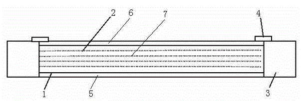
[0049] For the rubber dam bag of this embodiment, refer to the attachment Figure 1-3 The rubber dam bag of this embodiment is suitable for water-filled rubber dams. The dam bag has a height of 1.5m, a bottom length of 16.9m, an internal pressure ratio of 1.25, a slope ratio of 1:0.5, and a dam bag size: 6.084m× 21.3m, dam bag thickness 10mm;

[0050] When designing, according to the dam bag size 6.084m×21.3m, width plus 1%-2% shrinkage, length plus 5%-10% shrinkage, the design size is 6.2m×22.3m.

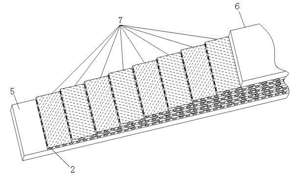
[0051] The rubber dam bag of this embodiment includes a dam bag body 1 composed of a lower rubber surface 5 and an upper rubber surface 6. The special feature is that a multi-layer skeleton layer is provided between the lower rubber surface 5 and the upper rubber surface 6. 7. The skeleton layer 7 includes a plurality of cords 2 spaced apart and arranged obliquely. The cords of the adjacent skeleton layers 7 have symmetrical cords. The lower rubber surface 5, the upper rubber surface 6 ...

Embodiment 2

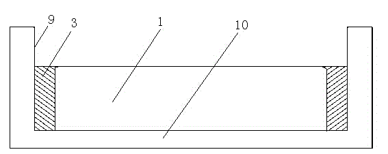
[0071] This embodiment refers to the attached Figure 4-5 The difference between this embodiment and embodiment 1 is that the rubber dam bag includes a dam bag body 1 composed of a lower rubber surface 5 and an upper rubber surface 6. There are multiple rubber dam bags between the lower rubber surface 5 and the upper rubber surface 6. The skeleton layer 7 includes a plurality of cords 2 spaced apart and arranged obliquely. The cords of adjacent skeleton layers 7 have symmetrical cords. The lower rubber surface 5, the upper rubber surface 6 and the skeleton layer 7 are vulcanized Combined as a whole; both sides of the dam bag body 1 are provided with vulcanized airbags 11 integrated with it;

[0072] The installation process is different, the installation process of this embodiment is as follows:

[0073] 1), supplement vulcanization side airbag

[0074] Vulcanize the pre-vulcanized airbag 11 to both sides of the rim of the dam bag body 1;

[0075] 2), installation

[0076] The ope...


PUM


Abstract

The invention belongs to a dam bag and an installation technology thereof, and particularly relates to a rubber dam bag and an installation technology thereof. The rubber dam bag comprises a dam bag body composed of a lower rubber surface and an upper rubber surface, wherein multiple frame layers are arranged between the lower rubber surface and the upper rubber surface, each frame layer comprises multiple tire cords arranged obliquely at intervals, the oblique directions of tire cords of adjacent frame layers are symmetrical, and the lower rubber surface, the upper rubber surface and the frame layers are combined by means of the vulcanization technology. The rubber dam bag is long in service life and high in flexibility, the strength of the frame layers can be reduced, bending of the linear section and vertical wall section of the dam bag is avoided, the dam bag does not need to be arranged on a vertical wall to be anchored during installation, air tightness is improved, and water retaining effect is improved.

Description

Technical field [0001] The invention belongs to a dam bag and an installation process thereof, in particular to a rubber dam bag and an installation process thereof. Background technique [0002] At present, the production and installation method of straight-wall slope dams is based on the length of the foundation plus the height of the wall. After the production of the dam bag is completed, anchor the dam bag from one straight wall to the other straight wall. The installation form mainly has the following problems: The dam bag at the conversion position between the straight section and the straight wall is seriously discounted, and the stress concentration point of the dam bag is prone to appear in this position, which causes the dam bag to be easily aging and damaged, and its service life is affected. Obviously, the dam shape is not beautiful enough and the water retaining effect of the discount position is poor. Summary of the invention [0003] The purpose of the present inv...

Claims


Application Information

Patent Timeline
Patent Type & Authority Applications(China)
IPC IPC(8): E02B7/00
CPCE02B7/005
Inventor 洪志强李玲杨孝栋
Owner YANTAI SUNNY RUBBER
Why Eureka
Try Eureka