Light conduction column capable of conducting multiple LED light sources

A technology of LED light source and light guide column, which is applied in the field of light guide column, and can solve problems such as too dark, uneven light brightness on the light-emitting surface, and excessively bright light-emitting surface

Inactive Publication Date: 2015-08-26
NANNING FUGUI PRECISION IND CO LTD
View PDF7 Cites 5 Cited by
  • Summary
  • Abstract
  • Description
  • Claims
  • Application Information

AI Technical Summary

Problems solved by technology

However, in the traditional method, due to the different placement of the LED light source, the brightness of the li...

Method used


Image

  • Light conduction column capable of conducting multiple LED light sources
  • Light conduction column capable of conducting multiple LED light sources
  • Light conduction column capable of conducting multiple LED light sources

Examples


Embodiment Construction

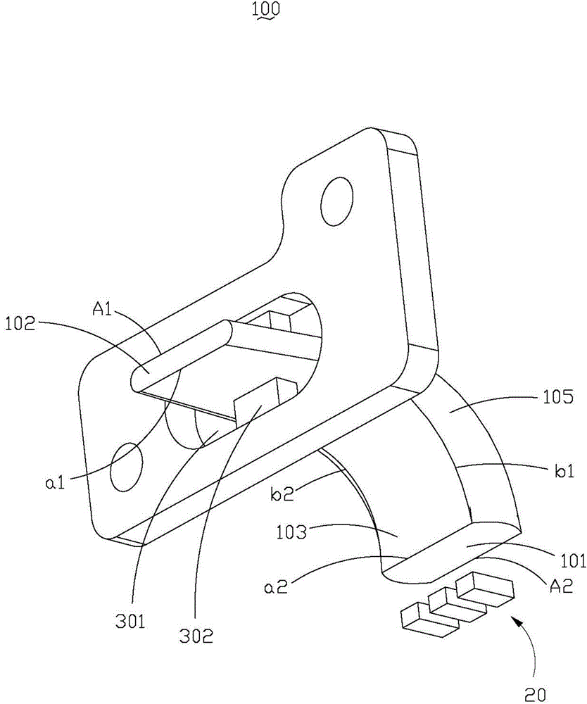
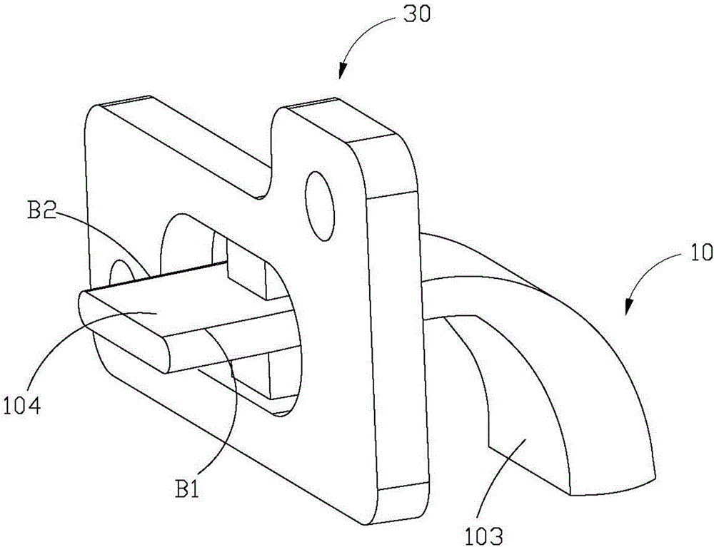
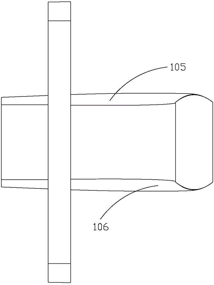
[0026] Such as figure 1 , figure 2 with image 3 As shown, a light source device 100 provided by the present invention includes a light guide rod 10 that can conduct multiple LED light sources, a plurality of LED light sources 20, and a connecting plate 30. The light guide rod 10 is connected to the connecting plate 30, and the light guide rod 10 passes through The connecting plate 30 and the product shell are connected to each other. The light guide rod 10 includes a light incident surface 101, a light exit surface 102, a first surface 103, a second surface 104, a first parabolic side wall 105 and a second parabolic side wall 106. The first surface 103 and the second surface 104 are arranged opposite to each other. parallel. The first parabolic sidewall 105 and the second parabolic sidewall 106 are oppositely disposed and located between the first surface 103 and the second surface 104. The first surface 103, the second surface 104, the first parabolic sidewall 105 and the s...


PUM


Abstract

A light pipe for transmitting lights includes a light incident wall, a light radiation wall, a first side wall, and a second side wall, the light incident wall opposite the light radiation wall, the first side wall opposite the second side wall, the first side wall and the second side wall are connected between the light incident wall and the light radiation wall, respectively. the first side wall and the second side wall are parabolic and having focal points between the first side wall and the second side wall, the first side wall and the second side wall are parabolic making the lights passing through the light radiation wall be uniformly distributed.

Description

Technical field [0001] The invention relates to a light guide pole structure, in particular to a light guide pole capable of conducting multiple LED light sources. Background technique [0002] In electronic products, LED light sources are often used as light-emitting sources, and light signals are transmitted to the housing through the light guide to display the corresponding electronic product status. A traditional single light guide can only transmit a single LED light source. If multiple LED light sources are conducted, multiple light guides need to be connected together for transmission. Some methods are also used to place multiple LEDs on the light incident surface of a traditional single light guide. light source. However, in the traditional method, due to the different placement of the LED light source, the brightness of the light emitting surface will be uneven, and the light emitting surface may be partially too bright or too dark. Summary of the invention [0003] In ...

Claims


Application Information

Patent Timeline
IPC IPC(8): F21V8/00
CPCG02B6/0006G02B6/0008G02B6/002G02B6/3644G02B6/4214G02B6/4219G02B6/4243G02B6/0068G02B6/0073G02B6/0091
Inventor 邱显桓钟向焜
Owner NANNING FUGUI PRECISION IND CO LTD
Why Eureka
Try Eureka