MEMS (Micro Electromechanical System) switching device, array substrate, manufacturing method of array substrate and display device

A switching device and switching element technology, which can be applied to static indicators, nonlinear optics, instruments, etc., can solve the problem of no display device, etc., and achieve the effect of good display effect and low cost.

Active Publication Date: 2015-08-26
BOE TECH GRP CO LTD
View PDF5 Cites 11 Cited by
  • Summary
  • Abstract
  • Description
  • Claims
  • Application Information

AI Technical Summary

Problems solved by technology

[0004] In the current MEMS display field, there is no display device that can flexibly switch the three display modes of transmission mode, reflection mode and transflective mode.

Method used


Image

  • MEMS (Micro Electromechanical System) switching device, array substrate, manufacturing method of array substrate and display device
  • MEMS (Micro Electromechanical System) switching device, array substrate, manufacturing method of array substrate and display device
  • MEMS (Micro Electromechanical System) switching device, array substrate, manufacturing method of array substrate and display device

Examples


Embodiment Construction

[0051] In order to meet the display requirements of different scenarios, so that the display device can be flexibly switched in three display modes: transmission mode, reflection mode and transflective mode, embodiments of the present invention provide a MEMS switch device, an array substrate and a manufacturing method thereof , a method for driving a display device and a MEMS switch device. In order to make the purpose, technical solution and advantages of the present invention clearer, the following examples are given to further describe the present invention in detail.

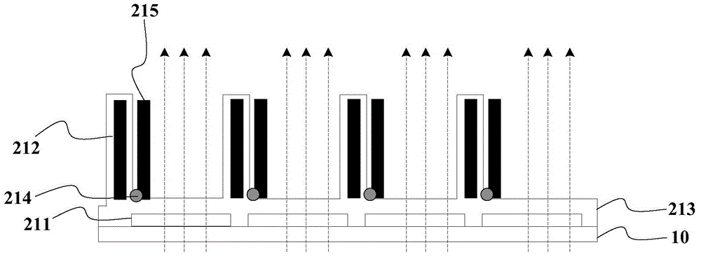
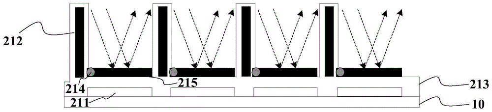
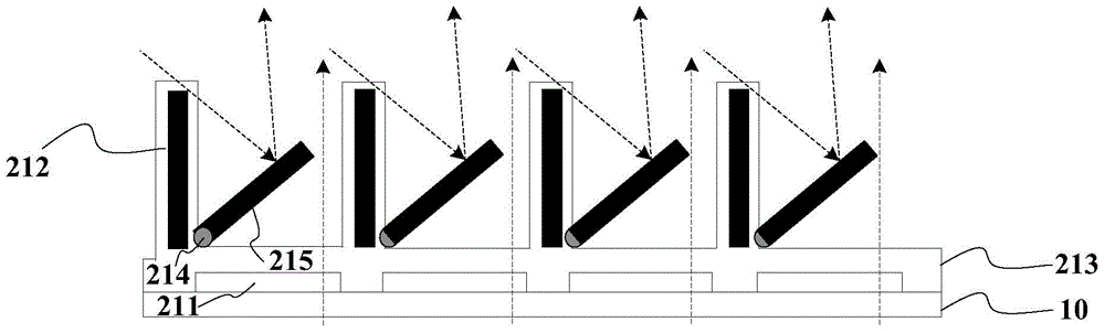
[0052] like Figure 1 to Figure 4 As shown, the MEMS switch device 20 provided by the embodiment of the present invention ( Figure 1 to Figure 3 , only four MEMS switching devices are shown above the base substrate 10), including light valve elements 21 and switching elements 22, wherein:

[0053]The light valve element 21 includes: a first sensing electrode 211 perpendicular to the light transmission di...


PUM


Abstract

The invention discloses an MEMS (Micro Electromechanical System) switching device, an array substrate, a manufacturing method of the array substrate, a display device and a driving method of the MEMS switching device. The display device can be flexibly switched among a transmission mode, a reflection mode, a reflection mode and a semi-transmission and semi-reflection mode to meet display requirements of different scenes. The MEMS switching device comprises a light valve element and a switching element, wherein the light valve element comprises a first induction electrode perpendicular to light transmission direction, a second induction electrode parallel to the light transmission direction, an insulating layer covering the first induction electrode and the second induction electrode and insulating the first induction electrode and the second induction electrode, an anchoring part positioned at the junction of the first induction electrode and the second induction electrode and a moving grating connected with the anchoring part; the moving grating can reflect ambient light or light emitted by a front light source when forming an included angle with the second induction electrode; when electric field voltage is applied to the light valve element, the light valve element works in the transmission mode, the reflection mode or the semi-transmission and semi-reflection mode.

Description

technical field [0001] The present invention relates to the field of display technology, in particular to a MEMS (Micro-electromechanical System, micro-electromechanical system) switch device, an array substrate and a manufacturing method thereof, a display device and a driving method for the MEMS switch device. Background technique [0002] Liquid crystal display devices can be divided into transmissive, reflective and transflective according to different light sources used. Among them, the transmissive liquid crystal display device uses the backlight as the light source, which has the advantage that it can display bright images in a dark environment, but the disadvantage is that the light that can pass through accounts for a small proportion of the light emitted by the backlight, and the power consumption is high; reflection The type liquid crystal display device uses the front light source or the ambient light source as the light source, and uses metal or other material l...

Claims


Application Information

Patent Timeline
Patent Type & Authority Applications(China)
IPC IPC(8): G02F1/1343G02F1/133
CPCG02F1/13306G02F1/134309G02F2201/12
Inventor 李会崔贤植林允植
Owner BOE TECH GRP CO LTD
Why Eureka
Try Eureka