Method of realizing beam forming and base station

A beamforming matrix, base station technology, applied in space transmit diversity, radio transmission systems, electrical components, etc., can solve the problems of a large number of iterative steps and low engineering implementation.

Inactive Publication Date: 2015-08-26
ZTE CORP
View PDF3 Cites 11 Cited by
  • Summary
  • Abstract
  • Description
  • Claims
  • Application Information

AI Technical Summary

Problems solved by technology

However, because the algorithm requires a large number of iterative steps, the engineering realization is not high

Method used


Image

  • Method of realizing beam forming and base station
  • Method of realizing beam forming and base station
  • Method of realizing beam forming and base station

Examples


Embodiment 1

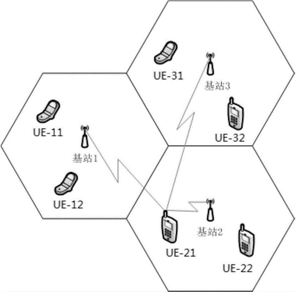
[0183] In this embodiment, a cooperative cluster consisting of three cells is considered. Each cell includes a 2-antenna base station and two single-antenna UEs. When a UE receives services from the base station in this cell, it will also be interfered by the base stations in the other two cells. The channel in the disclosed embodiment is a randomly generated Gaussian channel with a path loss coefficient of 2. Typically, the error model parameters in the disclosed embodiments are set to Attached below image 3 And attached Figure 4 Specific embodiments of the present invention will be described in detail.

[0184] image 3It is an application scene diagram of the present invention, including: base station 1, base station 2, base station 3, and users served by base station 1 (UE-11, UE-12), users served by base station 2 (UE-21, UE- 22) and users (UE-31, UE-32) served by base station 3.

[0185] Figure 4 It is a schematic diagram of the cell cooperation mechanism in t...


PUM


Abstract

A method and base station for enabling beamforming, wherein the method for enabling beamforming comprising: establishing a downlink beam optimization model according to an integrated channel error model and a downlink model; obtaining an optimal beamforming matrix optimization goal according to the established downlink beam optimization model; respectively obtaining the channel matrixes of the service cell in which the base station is located and the cells exclusive of the service cell in the cooperative cluster in which the base station is located and the nonideal parameters respectively corresponding to each channel matrix; obtaining a beamforming matrix for the base station according to the obtained channel matrixes and the nonideal parameters respectively corresponding to each channel matrix and the optimal beamforming matrix optimization goal, the base station transmitting downlink data according to the obtained beamforming matrix. The beamforming method and base station effectively suppress TDD system channel error, eliminate complex iteration calculation steps, and can effectively suppress inter-cell interference.

Description

technical field [0001] The invention relates to multi-cell multiple-input single-output (MISO, Multi-Input Single-Output) wireless communication technology, in particular to a method for realizing beamforming based on a time-division multiplexing (TDD) system and a base station. Background technique [0002] The evolution system of the third-generation mobile communication technology (3G) represented by the long-term evolution (LTE) has realized a phased change of mobile communication after 3G. In order to further meet the requirements of the International Telecommunication Union's advanced international communication technology (ITU IMT-Advanced), and also as an evolution of LTE technology, 3GPP adopted the enhanced technology of LTE (LTE-A, LTE-Advanced) as the fourth generation mobile communication A proposal for a technical (4G) standard. Multi-cell MIMO is one of the key technologies of LTE-A. At the same time, in order to meet the requirements of high system speed an...

Claims


Application Information

Patent Timeline
Patent Type & Authority Applications(China)
IPC IPC(8): H04B7/06
CPCH04B7/0617
Inventor 李杰吴凤娟任大孟徐岩松
Owner ZTE CORP
Why Eureka
Try Eureka