Device for producing milk foam

A milk foam and milk technology, which is applied in beverage preparation devices, applications, kitchen utensils, etc., can solve the problems of unreliable milk foam and difficult to accurately control, and achieve the effect of long service life

Active Publication Date: 2015-08-26
SOC DES PROD NESTLE SA
View PDF6 Cites 13 Cited by
  • Summary
  • Abstract
  • Description
  • Claims
  • Application Information

AI Technical Summary

Problems solved by technology

These factors are difficult to understand and not easy to precisely control without building more complex devices
Consequently, the milk froth of many simple prior ar

Method used


Image

  • Device for producing milk foam
  • Device for producing milk foam
  • Device for producing milk foam

Examples


Embodiment Construction

[0052] Although the milk and air supply circuits are part of the device according to the invention, for simplicity, the Figures 3 to 7 They are not shown in .

[0053] image 3 A device 1 for generating milk froth according to a first embodiment of the invention is schematically shown. The device 1 comprises an at least partially hollow outer cylinder 2, wherein the hollow defines an inner diameter o of the outer cylinder. Inside the outer cylinder 2 , that is, in the hollow portion, an inner cylinder 3 concentric with the outer cylinder 2 is provided. The inner cylinder 3 has an outer diameter i. The outer cylinder 2 and the inner cylinder 3 are rotatable relative to each other about a common axis of rotation. To this end, preferably, the inner cylinder 3 can surround image 3 The axis of rotation indicated by the dotted line in the middle rotates, that is, the inner cylinder 3 is the rotor. The outer cylinder 2 is preferably fixed, ie the outer cylinder 2 is preferabl...


PUM

PropertyMeasurementUnit
Diameteraaaaaaaaaa

Abstract

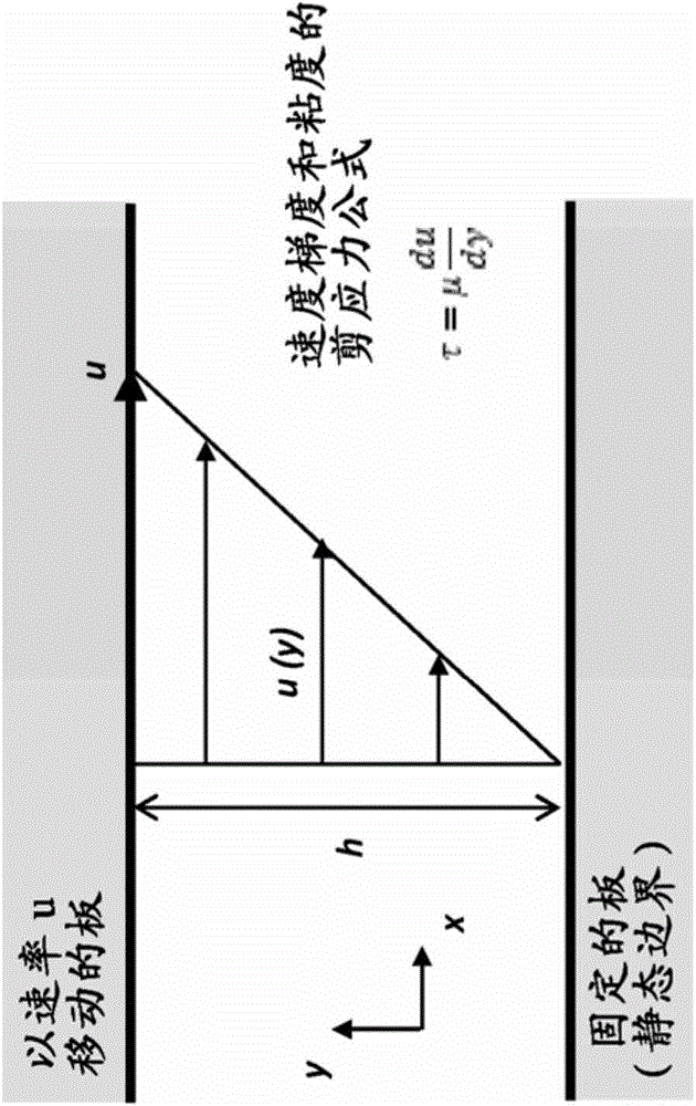
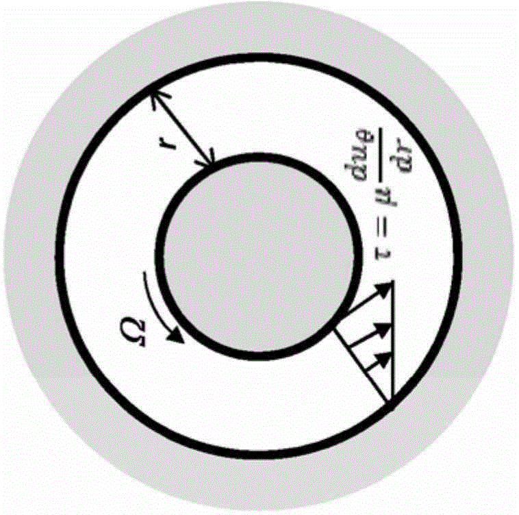
The present invention provides a device 1 for producing milk foam, which makes use of Couette flow and a high shear stress that is accordingly applied to a milk-air mixture in a gap between a housing, in particular an outer cylinder, and a rotating element rotating arranged therein. The device further comprises a milk supply circuit supplying the fluid inlet with milk and an air supply circuit supplying the fluid inlet with air, both supply circuits being independent from each other.

Description

technical field [0001] The invention relates to a device for frothing a fluid, preferably for producing milk froth. In particular, the device is designed in such a way that it can be positioned within a fluid flow path to generate foam. The device of the present invention uses the high shear energy experienced by the fluid in the device as foaming energy for foam generation. Background technique [0002] In the prior art, devices are known for producing milk froth, wherein the frothing of the milk is usually carried out in a batch process. For example, a device is known which has a reservoir into which milk can be filled. A rotating part in the reservoir, such as a stirrer arranged at the bottom of the reservoir, causes frothing of the milk. However, such devices for producing milk froth only produce a predetermined amount of milk froth at the same time (ie in one batch process). Thereafter, the unit needs to be emptied, preferably cleaned, and refilled with milk before ...

Claims


Application Information

Patent Timeline
IPC IPC(8): A47J31/46A47J43/00
CPCA47J31/4485A47J31/46B01F23/2351B01F2101/07A23C7/00A47J31/4496
Inventor A·佩雷特斯A·约阿基姆A·佩林
Owner SOC DES PROD NESTLE SA
Why Eureka
Try Eureka