
Eureka
For R&D, Eureka makes reading and utilizing patents & technical documents easy.
Eureka AIR
Designed for self-driven R&D workflows. Generate viable solutions, solve complex R&D challenges, empower your innovation with AI.

Eureka Materials
Designed for material experts only. Revolutionize your material R&D, from search, analyze, to developing new materials.

TechResearch
Generate reliable direction feasibility study reports for your R&D in just a few steps.

TechSeek
Discover and master advanced knowledge NOW. Basics, ideas, possibilities, all at once.

TechMind
As an expert in R&D Theories, TechMind can generates customized viable solutions instantly.

TechRisk
Analyze your overall solution with one click, know your potential R&D risks in advance.

TechMonitor
Get weekly tech updates, stay abreast of the latest tech innovations and key insights.
Column Casting Distal Fixing System with Telescoping Tube Structure
A fixed system and telescopic tube technology, which is applied in the field preparation of building components, construction, building construction, etc., can solve the problems of poor pouring quality, unstable pouring, long construction period, etc., so as to reduce the difficulty of operation and work Strength, avoiding safety accidents, simple and convenient operation
- Summary
- Abstract
- Description
- Claims
- Application Information
AI Technical Summary
Problems solved by technology
Method used
Image

Examples
Embodiment 1
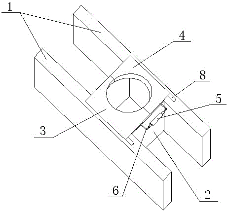
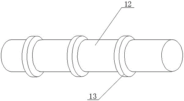
[0025] Such as Figure 1~Figure 7 As shown, the column pouring distal fixing system with a telescopic cylinder structure described in this embodiment includes a support frame and a discharge cylinder 12 installed on the support frame. The outer wall of the discharge cylinder 12 is provided with a plurality of annular Protrusion 13, the concrete quantity of protrusion 13 can be determined according to construction requirements, and support frame comprises two horizontal boards 1 and two middle boards 2, and two horizontal boards 1 are arranged in parallel, and two middle boards 2 are fixed on two horizontal boards. The middle part of the board 1, and the two middle boards 2 are perpendicular to the two horizontal boards 1, the middle parts of the two horizontal boards 1 are respectively provided with a relative step 11, and one of the same ends of the two steps 11 is respectively provided with a plug Hole A8, the other end of the same direction is respectively provided with a U...
Embodiment 2
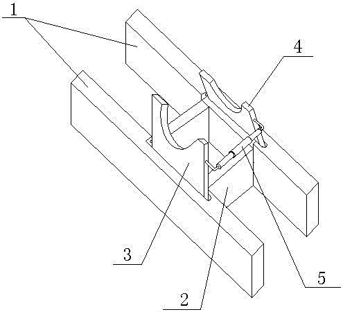
[0029] This embodiment is basically the same as Embodiment 1, the difference is that the diameter of the circle where the notches on the left clamping plate 3 and the right clamping plate 4 of this embodiment is equal to the outer diameter of the discharge cylinder 12, so that the left clamping plate 3 and the right clamping plate 4 are located. The right splint 4 clamps the discharge cylinder 12 more reliably, making concrete pouring more stable and reliable.
Embodiment 3
[0031] This embodiment is basically the same as Embodiment 1, except that this embodiment limits the angle between the inner surface of the step 11 and the step surface to 70 to 80 degrees. The so-called inner surface of the step 11 refers to the left splint After 3 or the right splint 4 is fully opened, a surface that will be in contact with the upper surface of the left splint 3 or the right splint 4 is designed to form an angle of 70 to 80 degrees with the step surface, that is, the inner surface and the vertical The angle between the straight faces is 10-20 degrees, so that when the left splint 3 and the right splint 4 are fully opened, under the action of the inner side, the opening angle of the left splint 3 and the right splint 4 will not exceed 90 degrees. That is, the left splint 3 and the right splint 4 always have a tendency to fall and close automatically, and then after we push or pull the left splint 3 and the right splint 4 out of the slot 7, the left splint 3 an...
PUM
 Abstract
Description
Claims
Application Information
 - R&D Engineer
- R&D Manager
- IP Professional
- Industry Leading Data Capabilities
- Powerful AI technology
- Patent DNA Extraction
Browse by: Latest US Patents, China's latest patents, Technical Efficacy Thesaurus, Application Domain, Technology Topic, Popular Technical Reports.
© 2024 PatSnap. All rights reserved.Legal|Privacy policy|Modern Slavery Act Transparency Statement|Sitemap|About US| Contact US: help@patsnap.com