Eureka AIR delivers breakthrough ideas for toughest innovation challenges, trusted by R&D personnel around the world.

Lifting appliance

A technology of spreaders and hangers, applied in the field of spreaders, can solve problems such as decoupling, inability to fully see the specific situation of each pair of claws from a viewing angle, and positioning of lifting parts

Pending Publication Date: 2022-04-05
浙江嘉兴御豪智能装备有限公司
View PDF0 Cites 0 Cited by
  • Summary
  • Abstract
  • Description
  • Claims
  • Application Information

AI Technical Summary

Problems solved by technology

[0002] Most of the existing spreaders are claw-type spreaders. This kind of spreader is difficult to carry out lifting work in a narrow space, and because its mechanical mechanism is too simple, and the operator who controls the spreader sits in the control room of the driving, the other The specific situation of each pair of claws cannot be fully seen from the angle of view, so it is difficult to locate the lifting position with the parts to be lifted, and it is very easy to hang empty or unhook, posing a big safety hazard
In addition, because the claws of the claw-type spreader are usually grasped from the outside of the object to be lifted, a large enough gap must be reserved between adjacent objects to be lifted, so that the objects to be lifted cannot be arranged closely
Especially for the lifting operation of the concrete prefabricated pile mold, the prefabricated pile mold needs to be lifted in a narrow space (such as a steam curing pond), and the existing claw-type spreader is completely incompetent

Method used


Image

  • Lifting appliance
  • Lifting appliance
  • Lifting appliance

Examples


Embodiment Construction

[0041] The following clearly and completely describes the technical solutions in the embodiments of the present invention. Obviously, the described embodiments are only part of the embodiments of the present invention, not all of them. Based on the implementation manners in the present invention, all other implementation manners obtained by persons of ordinary skill in the art without making creative efforts belong to the scope of protection of the present invention.

[0042] It should be noted that when a component is said to be "connected to" another component, it may be directly connected to the other component or there may be an intervening component. When a component is said to be "set on" another component, it may be set directly on the other component or there may be an intervening component at the same time. When a component is said to be "fixed" to another component, it may be directly fixed to the other component or there may be an intervening component at the same t...


PUM


Abstract

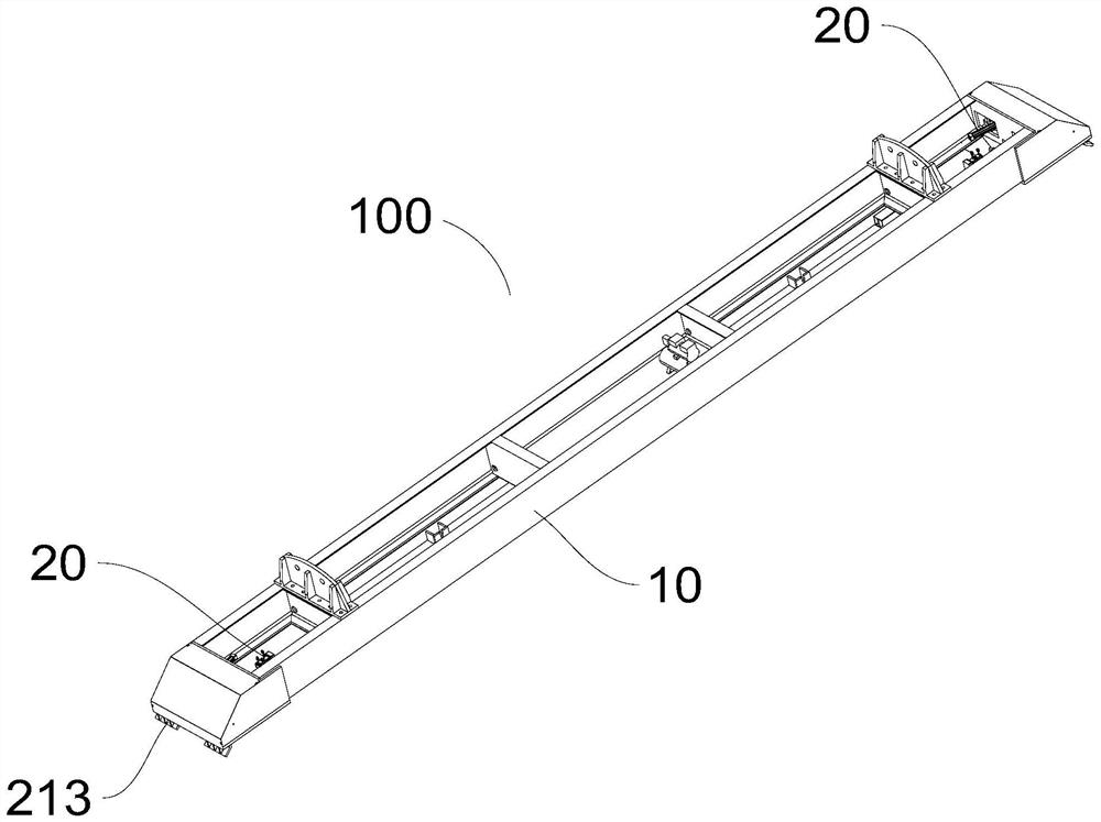
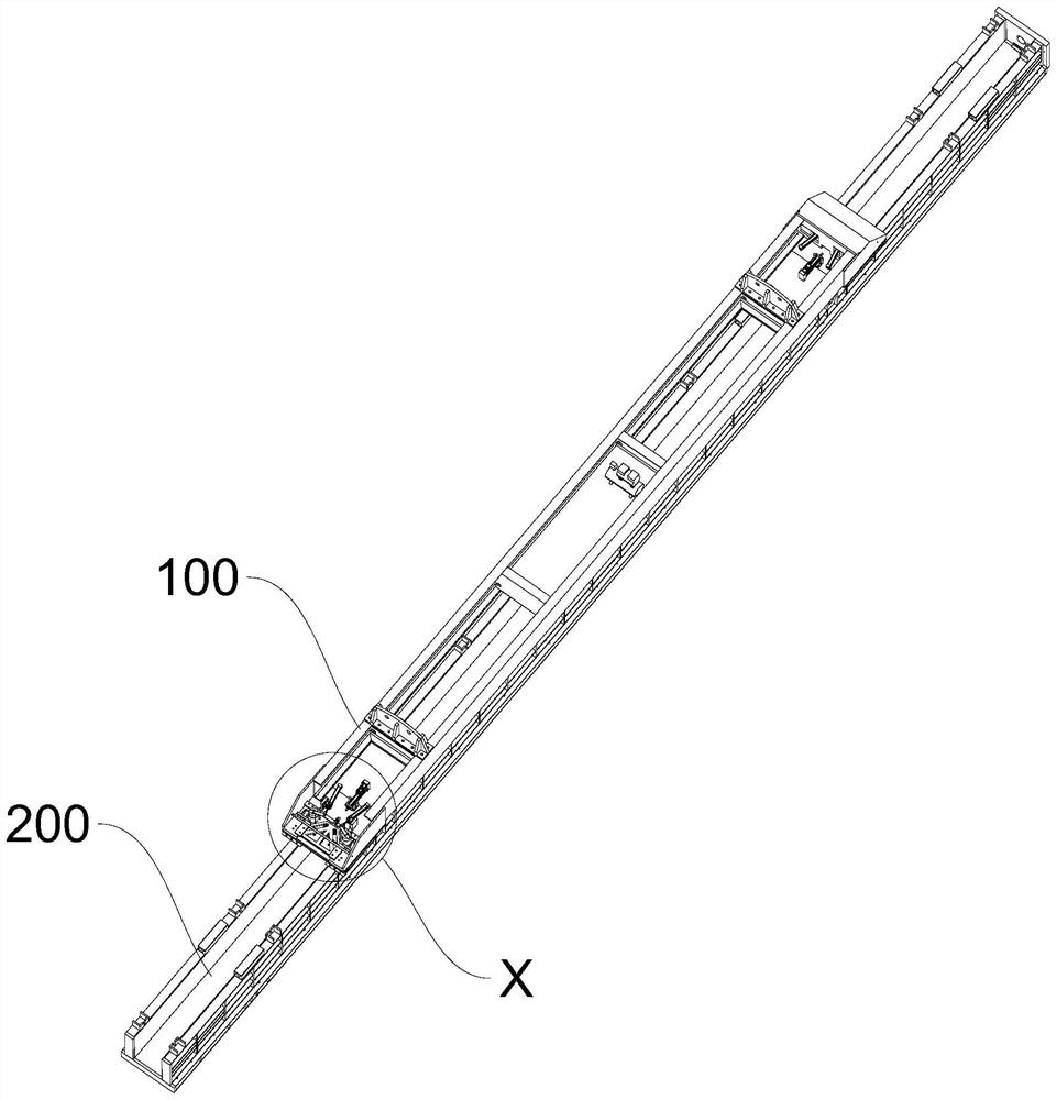
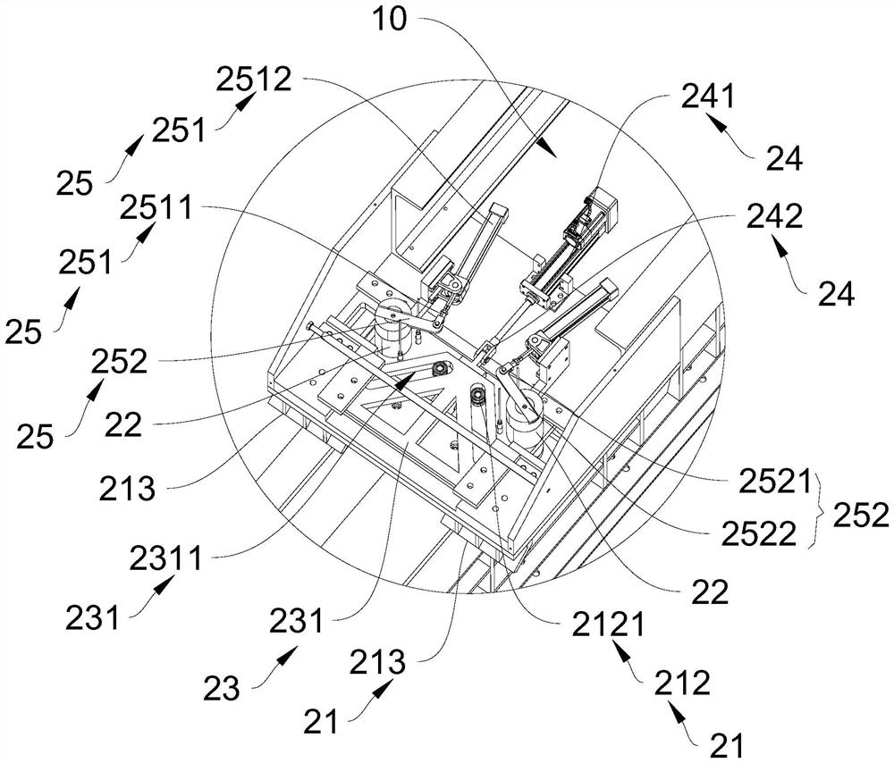
The lifting appliance comprises a lifting appliance body and at least one lifting device arranged on the lifting appliance body, each lifting device comprises a positioning mechanism and at least two sets of lifting lock mechanisms symmetrically arranged on the lifting appliance body, the lifting lock mechanisms and the positioning mechanisms are arranged at the bottom of the lifting appliance body in a protruding mode, and the lifting lock mechanisms are used for being connected with a part to be lifted; and the positioning mechanism is used for positioning the two groups of lifting lock mechanisms so as to align the lifting position on the to-be-lifted piece. According to the lifting appliance, the lifting lock mechanism arranged at the bottom of the lifting appliance body in the protruding mode can enable the lifting appliance to conduct lifting work in a small space and is not limited by the narrow stacking and placing space of the to-be-lifted pieces, and the positioning mechanism can assist in positioning the lifting position between the lifting lock mechanism and the to-be-lifted pieces; the lifting lock mechanism and the to-be-lifted piece can be accurately connected, the phenomenon of empty lifting or unhooking is avoided, and the reliability and the safety of the lifting appliance are improved.

Description

technical field [0001] The invention relates to the field of slings, in particular to a sling. Background technique [0002] Most of the existing spreaders are claw-type spreaders. This kind of spreader is difficult to carry out lifting work in a narrow space, and because its mechanical mechanism is too simple, and the operator who controls the spreader sits in the control room of the driving, the other The angle of view cannot fully see the specific situation of each pair of claws, so it is difficult to locate the lifting position with the parts to be lifted, and it is very easy to hang empty or unhook, posing a great safety hazard. In addition, because the claws of the claw-type spreader are usually grasped from the outside of the object to be lifted, a large enough gap must be reserved between adjacent objects to be lifted, so that the objects to be lifted cannot be arranged closely . Especially for the lifting operation of the concrete prefabricated pile mold, the pref...

Claims


Application Information

Patent Timeline
IPC IPC(8): B66C1/10B66C1/66
Inventor 许万豪
Owner 浙江嘉兴御豪智能装备有限公司
Why Eureka
Eureka Blog
Learn More