Electric pole erection correcting support

A pole and pole-shaped technology, applied in the field of auxiliary tools for pole erection, can solve the problems of unfavorable mana, potential safety hazards, time-consuming and labor-intensive, etc., and achieve the effect of ensuring a safe distance and preventing injuries.

Inactive Publication Date: 2015-09-02
STATE GRID SHANDONG CHANGYI POWER SUPPLY +1
View PDF0 Cites 3 Cited by
  • Summary
  • Abstract
  • Description
  • Claims
  • Application Information

AI Technical Summary

Problems solved by technology

In this process, due to the need to match the direction of the cross arm, it is necessary to adjust the direction of the pole during the erection process. Since the pole has no force point during erection, it is not conducive to mana, and often requires two or more people to complete the work, which is time-consuming It is laborious, and during the operation, the staff is too close to the utility pole, which poses a safety hazard

Method used


Image

  • Electric pole erection correcting support

Examples


Embodiment 1

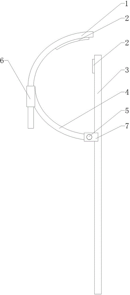
[0018] Embodiment 1: As shown in the drawings, the electric pole is erected with a correction bracket, including a rod-shaped part 3, an arc-shaped part 4 and a movable part 1, one end of the arc-shaped part 4 is connected with the rod-shaped part 3, and the other end of the arc-shaped part 4 is set There is a sleeve 6, one end of the movable part 1 passes through the sleeve 6, the length of the movable part 1 passing through the sleeve 6 is adjustable, and the other end of the movable part 1 is bent toward the direction close to the rod-shaped part 3.

[0019] Tensioners 2 are arranged on the movable part 1 and the rod-shaped part 3 . Of course, the tension member 2 can also be provided only on the movable part 1 or the rod-shaped part 3 .

[0020] The tension member 2 is an elastic member, and the elastic member is a rubber pad. In addition, the tension member 2 can also be configured as an air bag or a component with several sawtooths on its surface.

[0021] The tension ...


PUM


Abstract

The invention provides an electric pole erection correcting support. The electric pole erection correcting support is characterized in that the support comprises a rod-shaped part, an arc-shaped part and a moving part; one end of the arc-shaped part is connected with the rod-shaped part, a sleeve is arranged at the other end of the arc-shaped part, one end of the moving part penetrates through the sleeve, the length of the portion, penetrating out of the sleeve, of the moving part can be adjusted, and the other end of the moving part is bent in the direction close to the rod-shaped part. According to the electric pole erection correcting support, the direction of an electric pole can be corrected only by one-person operation, so that time and labor are saved, single-pole erection time is changed into five minutes from ten minutes originally, the sufficient safety distance is guaranteed, and harm to constructors when the electric pole is erected is completely eliminated.

Description

technical field [0001] The invention relates to an auxiliary tool for erecting electric poles, in particular to a correction bracket for erecting electric poles. Background technique [0002] When erecting the pole, it is necessary to first install the cross arm to the top of the pole, and then erect the pole. In this process, due to the need to match the direction of the cross arm, it is necessary to adjust the direction of the pole during the erection process. Since the pole has no force point during erection, it is not conducive to mana, and often requires two or more people to complete the work, which is time-consuming It is laborious, and during the operation, the staff is too close to the utility pole, which poses a safety hazard. Contents of the invention [0003] The purpose of the present invention is to overcome the shortcomings of the above-mentioned traditional technology, and provide a simple structure, easy to use, time-saving and labor-saving electric pole ...

Claims


Application Information

Patent Timeline
Patent Type & Authority Applications(China)
IPC IPC(8): E04H12/34
Inventor 于强刘周武海涛齐同飞李周鹏陈吉礼季勇李润欣高文梅张安波李振全韩伟闫栋
Owner STATE GRID SHANDONG CHANGYI POWER SUPPLY
Why Eureka
Try Eureka