Transformer internal partial discharge determination device and positioning method thereof

A partial discharge and measurement device technology, which is applied in the direction of testing dielectric strength, etc., can solve the problems of large transformer error and low cost performance, and achieve the effects of small calculation, fast convergence speed and high precision of direction measurement

Inactive Publication Date: 2015-09-02
ELECTRIC POWER RES INST STATE GRID SHANXI ELECTRIC POWER
View PDF6 Cites 5 Cited by
  • Summary
  • Abstract
  • Description
  • Claims
  • Application Information

AI Technical Summary

Problems solved by technology

[0003] The invention provides a transformer internal partial discharge measurement device and its positioning method, which solves the technical problems of large errors and low cost performance in the existing transformer partial discharge measurement

Method used


Image

  • Transformer internal partial discharge determination device and positioning method thereof
  • Transformer internal partial discharge determination device and positioning method thereof

Examples


Embodiment Construction

[0022] The present invention is described in detail below in conjunction with accompanying drawing:

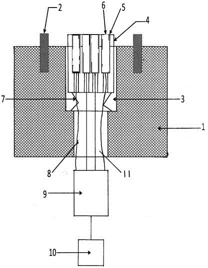
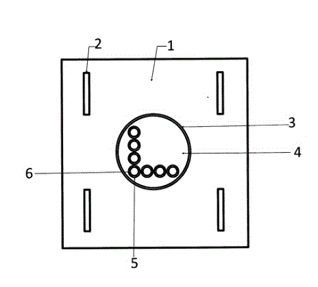
[0023] The invention provides a transformer internal partial discharge measuring device, comprising a transformer housing and a magnetic base 1, four magnet blocks 2 are fixedly arranged on the top surface of the magnetic base 1; A circular groove 3, in which a cylindrical sensor mount 4 is movably arranged; on the top surface of the cylindrical sensor mount 4, seven ultrasonic sensor sockets 5 arranged in an L-shape are arranged. An ultrasonic sensor 6 is plugged into the ultrasonic sensor socket 5; a compression spring 7 is arranged between the bottom surface of the circular groove 3 and the lower bottom surface of the cylindrical sensor mounting seat 4, and is arranged in the center of the bottom surface of the circular groove 3 Through hole 11, the ultrasonic signal lead-out line 8 of ultrasonic sensor 6 is electrically connected together with ultrasonic data collector 9 t...


PUM


Abstract

The invention discloses a transformer internal partial discharge determination device and a positioning method thereof, and solves the problems that existing transformer partial discharge determination is big in error and low in performance cost; the top of a cylinder sensor mount (4) is provided with 7 ultrasonic sensor plug slots (5) and ultrasonic sensors (6) arranged in an L-shape; a spring (7) is arranged between the bottom of a cylinder groove (3) and the bottom of the cylinder sensor mount (4); an ultrasonic signal leading-out wire (8) of the ultrasonic sensor (6) is electrically connected with an ultrasonic data collector (9) through a through hole (11); the ultrasonic data collector (9) is connected with a computer (10); L-shape array sensors are employed, a wideband focusing algorithm of a total least spuares (TLS) is used for focusing partial discharge ultrasonic broadband signals, and a narrowband direction finding algorithm combining a phase match principle with cloud optimization search is used for obtaining orientation information of a partial discharge source. The transformer internal partial discharge determination device is high in direction finding precision, and accurate in positioning.

Description

technical field [0001] The invention relates to a measuring device for partial discharge inside a transformer, in particular to a measuring device and a measuring method for partial discharge inside a transformer. Background technique [0002] The detection and precise location of transformer partial discharge are of great significance to timely discovering latent insulation defects inside electrical equipment and preventing accidents. The traditional transformer partial discharge location method is to measure the position of the partial discharge point inside the transformer through an ultrasonic sensor moving back and forth on the outer wall of the transformer when the partial discharge abnormality occurs in the transformer. This measurement method has poor measurement accuracy and low work efficiency. The problem. The existing technology starts to adopt the method of arranging ultrasonic array sensors on the surface of the transformer to measure the partial discharge po...

Claims


Application Information

Patent Timeline
Patent Type & Authority Applications(China)
IPC IPC(8): G01R31/12
Inventor 刘新元郑惠萍宋述勇薛敏杨尉薇张悦白瑞郝鑫杰王玮茹曲莹张颖周隽
Owner ELECTRIC POWER RES INST STATE GRID SHANXI ELECTRIC POWER
Why Eureka
Try Eureka