Stator for motor and method for manufacturing same

A motor and stator technology, applied in the field of improvement of motor stators, can solve problems such as bending of connecting wires, lengthening of motor axial direction, decrease in circularity of annular shape, etc., achieving high reliability, shortening distance, and preventing short circuit Effect

Inactive Publication Date: 2015-09-02
NIDEC TECHNO MOTOR CORP
View PDF9 Cites 4 Cited by
  • Summary
  • Abstract
  • Description
  • Claims
  • Application Information

AI Technical Summary

Problems solved by technology

[0006] However, if the resin is also formed on the mating surfaces of the adjacent split iron cores when the insulator is insert-molded, there will be a problem that the roundness of the bent ring shape will decrease.
On the other hand, if the exposed portion of the iron core not covered by the resin is located near the mating surface, the connecting wires arranged across the split iron core may be bent when the iron core is bent, and there is a possibility that it may not be covered by the insulating material. When the iron core near the mating surface contacts and a short circuit occurs
[0007] A method of extending the distance from the connecting wire to the iron core sufficiently so that the bent connecting wire does not come into contact with the stator core is also considered, but this also causes the problem that the axial length of the motor becomes longer.

Method used


Image

  • Stator for motor and method for manufacturing same
  • Stator for motor and method for manufacturing same
  • Stator for motor and method for manufacturing same

Examples


Embodiment Construction

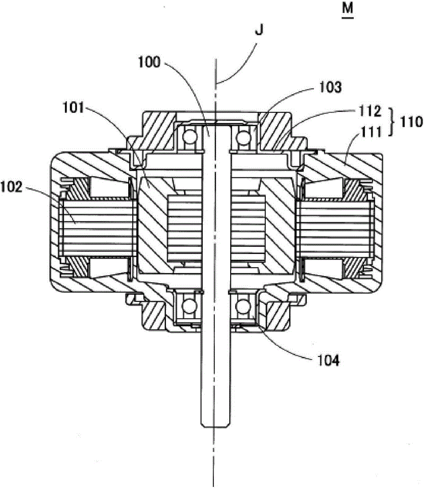
[0053] One embodiment illustrated in the present application will be described below with reference to the drawings. In this specification, the direction of the central axis J of the motor is described as the up-down direction for convenience, but it does not limit the posture of the motor involved in the present invention during use, and the direction of the central axis J of the motor is simply referred to as " "Axial" refers to the radial direction and the circumferential direction centered on the central axis J as "radial" and "circumferential" for short. The same applies to the stator and the stator core, and the directions that coincide with the axial, radial, and circumferential directions of the motor when they are assembled in the motor are referred to as "axial", "radial", and "circumferential" .

[0054] figure 1 It is a cross-sectional view of a motor M having an annular stator 102 according to an exemplary embodiment of the present application, and shows a cross...


PUM


Abstract

The invention relates to a stator for a motor and a method for manufacturing the same. The stator herein comprises: a stator core (2) which has an iron core connection portion (21) which connects more than two separation iron cores (20), an insulation piece (5) which is integratedly formed with the stator core (2) through an insert molding, wherein the separation iron core (20) has a yoke part (2y) which extends along a circumferential direction and a gear portion (2t) which extends radially from the yoke part (2y) o the inner side. The insulation piece (5) includes a gear insulation portion (53) which covers a coil mounting surface (2w) of the gear portion (2t) and a yoke insulation portion (51) which covers an upper surface of the yoke portion (2y) and an upper surface of the iron core connection portion (21). Therefore, the stator core (2) is not exposed from the upper surface of the yoke portion (2y) or from the upper surface of the iron core connection portion (21), which can prevent contact between a connection wire (4) and the stator core (2).

Description

technical field [0001] The present invention relates to a motor stator and a manufacturing method thereof, and more specifically relates to an improvement of a motor stator having a bendable strip-shaped stator core. Background technique [0002] In the inner rotor type motor, an annular stator is arranged radially outside of the rotor. In the stator, coils are attached to a stator core made of a soft magnetic material, and the core and winding wires are insulated by a resin insulating material. The iron core is composed of an annular core back and two or more teeth protruding radially inward from the inner peripheral surface of the iron core back, and the coil is mounted on the coil mounting surface of the teeth. [0003] As such an iron core, there is conventionally known a strip-shaped iron core having a substantially linear shape (for example, Japanese Laid-Open Publication No. 2003-329486). The strip-shaped iron core described in Japanese Laid-Open Publication No. 200...

Claims


Application Information

Patent Timeline
Patent Type & Authority Applications(China)
IPC IPC(8): H02K1/14H02K3/34H02K15/02
Inventor 吉田达也新井康之山本圣
Owner NIDEC TECHNO MOTOR CORP
Why Eureka
Try Eureka