
Interference source determination method and device

A determination method and technology for interference sources, applied in electrical components, wireless communication, etc., can solve the problems of difficulty in obtaining accurate and reliable detection results, difficulty in locating remote interference sources, and limited matching accuracy.

Active Publication Date: 2018-05-01
TD TECH COMM TECH LTD
View PDF4 Cites 0 Cited by
  • Summary
  • Abstract
  • Description
  • Claims
  • Application Information

AI Technical Summary

Problems solved by technology

[0004] However, as the propagation distance increases, there may be multiple interfering base stations for the target base station, and a large number of interfering signals are superimposed, while the Sync_DL is short and the matching accuracy is limited, and there are only 32 kinds of Sync_DL in the TD-SCDMA system, it is difficult to obtain accurate and reliable detection results, it is difficult to locate the far-end interference source

Method used


Image

  • Interference source determination method and device
  • Interference source determination method and device
  • Interference source determination method and device

Examples


Embodiment Construction

[0036] In order to make the objectives, technical solutions, and advantages of the embodiments of the present invention clearer, the technical solutions in the embodiments of the present invention will be described clearly and completely in conjunction with the accompanying drawings in the embodiments of the present invention. Obviously, the described embodiments It is a part of the embodiments of the present invention, not all the embodiments. Based on the embodiments of the present invention, all other embodiments obtained by those of ordinary skill in the art without creative work shall fall within the protection scope of the present invention.

[0037] image 3 It is a flowchart of Embodiment 1 of the interference source method of the present invention. This embodiment describes the present invention in detail from the perspective of an interfering base station that causes interference to the interfered base station. This embodiment is suitable for scenarios where the interfe...


PUM


Abstract

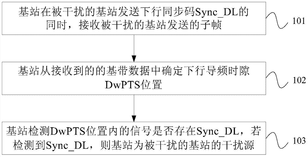
An embodiment of the present invention provides a method and device for determining an interference source. The method includes: the base station receives the subframe sent by the interfered base station while the interfered base station sends the downlink synchronization code Sync_DL; the base station receives the subframe from the received baseband data Determine the DwPTS position of the downlink pilot time slot; the base station detects whether there is Sync_DL in the signal within the DwPTS position, and if Sync_DL is detected, the base station is the interference source of the interfered base station. In the process of determining the interference source, only the interfered base station sends signals, and other remote base stations only receive signals while the interfered base station transmits signals, reducing the number of interference signals due to the superposition of a large number of interference signals, and the Sync_DL is short, the matching accuracy is limited, and it is difficult to Accurate and reliable detection results are obtained, it is difficult to locate the problem of the remote interference source, and the accurate determination of the base station causing interference to the target base station is realized.

Description

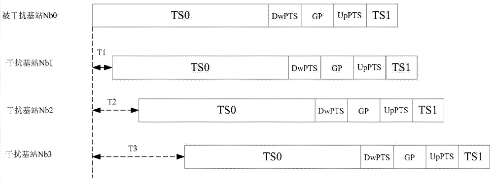
Technical field [0001] The present invention relates to wireless communication technology, in particular to a method and device for determining an interference source. Background technique [0002] The Time Division-Synchronization Code Division Multiple Access (TD-SCDMA) system adopts the Time Division Duplex (TDD) mode. figure 1 It is a schematic diagram of the subframe structure in the TD-SCDMA system in the prior art. Such as figure 1 As shown, each subframe is composed of 7 main time slots (TimeSlot, TS) and 3 special time slots. The 7 main time slots include uplink time slots and downlink time slots, as shown by the up and down arrows in the figure. Show; 3 special time slots are Downlink Pilot Time Slot (DwPTS), Uplink Pilot Time Slot (Uplink Pilot Time Slot, UpPTS) and Guard Interval (GP). In the TD-SCDMA system, different base stations maintain synchronization. As the propagation distance increases, for example, in the actual network environment, due to the influence of...

Claims


Application Information

Patent Timeline
Patent Type & Authority Patents(China)
IPC IPC(8): H04W24/00
Inventor 刘海义杨武涛
Owner TD TECH COMM TECH LTD
Learn More