Aeration device, operation method therefor, and water treatment apparatus

An operation method and technology of gas device, which are applied in water/sewage treatment, chemical instruments and methods, biological water/sewage treatment, etc., can solve the problem of membrane module function decline, gas turbulence for dispersing gas, expensive operation cost and equipment cost and other problems, to achieve the effect of high convenience and uniform air dispersion

Inactive Publication Date: 2015-09-02
MITSUBISHI CHEM CORP
View PDF10 Cites 5 Cited by
  • Summary
  • Abstract
  • Description
  • Claims
  • Application Information

AI Technical Summary

Problems solved by technology

[0006] However, in this case, in the vicinity of the terminal 11b in the diffuser pipe 11, turbulent flow of the gas for diffuser is likely to occur, and the diffuser from the diffuser holes 14 on the side of the terminal 11b cannot be uniformly diffused.
As a result, there is a problem that the membrane module cannot be cleaned sufficiently due to variation in the diffused air, and the function of the membrane module is reduced due to the adhesion (clogging) of sludge, etc.
[0007] In addition, the air diffuser usually operates under the condition of a large air volume, but there are the following problems: the larger the air volume of the air diffuser, the more expensive the operating cost and equipment costs due to the increase in power consumption
[0015] However, if Figure 12 to Figure 14 As shown, it is difficult to arrange the main piping and the diffuser pipe at a certain angle. In addition, in most cases, the calculation is based on experience and the location is judged, which lacks versatility.
In addition, there is a tendency for piping to be complicated

Method used


Image

  • Aeration device, operation method therefor, and water treatment apparatus
  • Aeration device, operation method therefor, and water treatment apparatus
  • Aeration device, operation method therefor, and water treatment apparatus

Examples


Embodiment 1

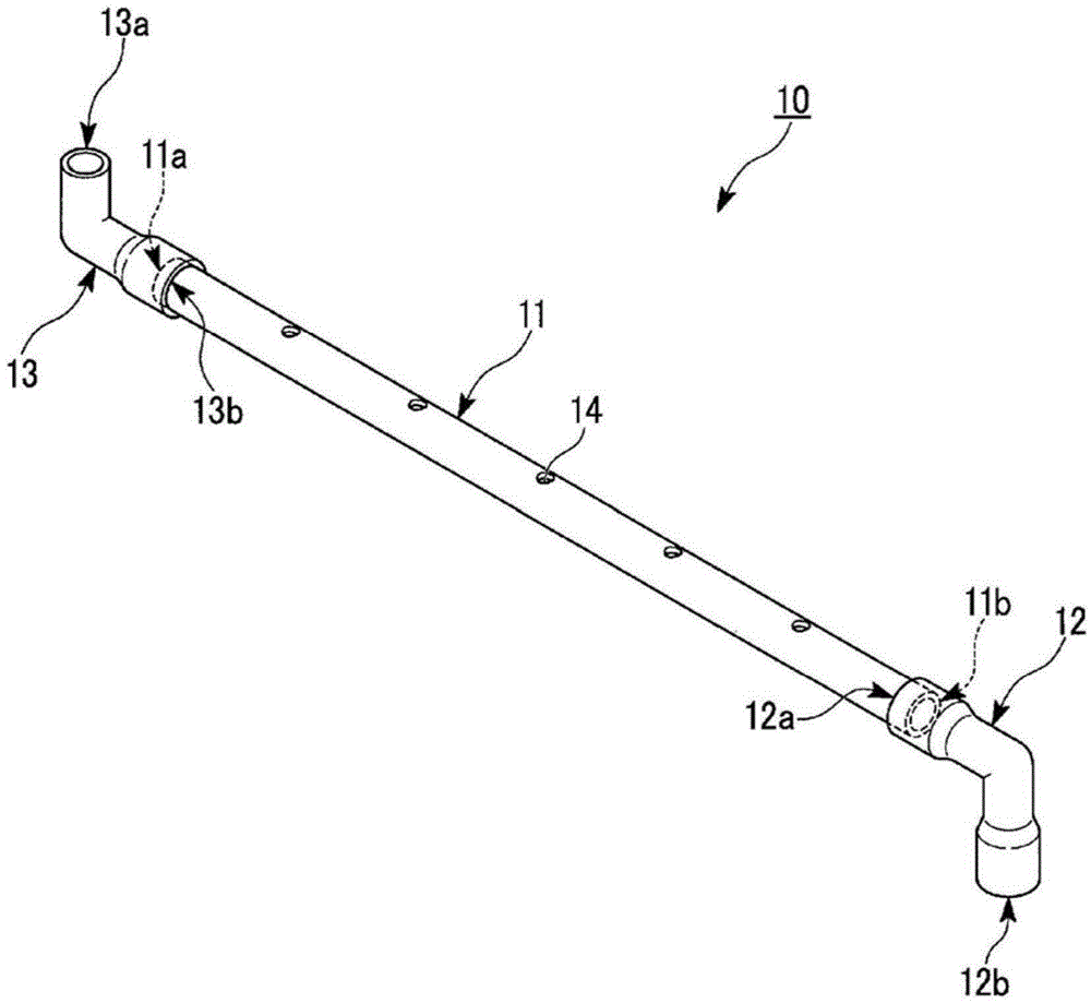
[0209] As the diffuser tube, a diffuser tube extending horizontally with an inner diameter D of 20.0 mm, a length L of 500 mm, and five circular diffuser holes with a diameter d of 6.0 mm at equal intervals was formed on the upper part.

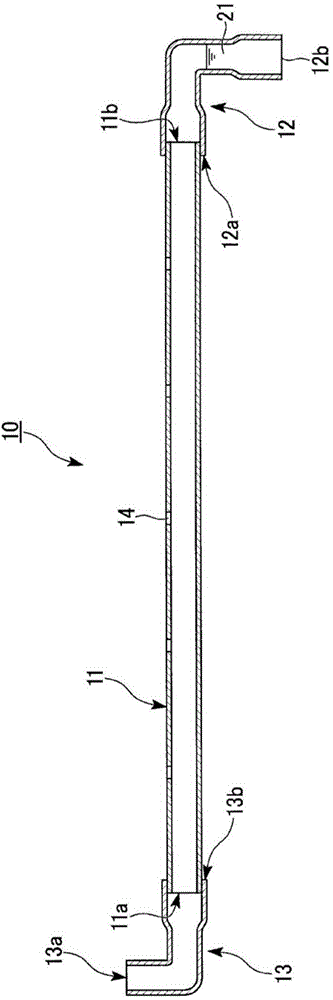
[0210] The base end of the diffuser pipe communicates with the other end of the connecting member. In addition, the other end is opened to the vertically lower side, and one end of the open pipe extending from the other end side to the longitudinally lower side is directly communicated with the end of the diffuser pipe, forming a figure 1 The diffuser 10 shown. As an open pipe, a 90° elbow is used.

[0211] The gas supply pipe of the gas supply device was connected to one end of the connection member, and air was supplied from the gas supply device to the diffuser pipe of the diffuser device at an air volume of 100 l / min.

[0212] The flow velocity of the air flowing in the diffuser pipe is 5.3m / s. In addition, the air volume of the air b...

Embodiment 2

[0219] The air-diffusing properties were evaluated in the same manner as in Example 1 except that the inner diameter D of the air-diffusing tube was changed to 13.0 mm. Table 1 and Table 2 show the results.

[0220] In addition, the flow velocity of the air flowing in the diffuser pipe is 12.6 mm. In addition, the air volume of the air blown out from each diffuser hole was 20.0 l / min per diffuser hole. In addition, the flow velocity of the air emitted from each diffuser hole is 10.6m / s, 10.7m / s, 11.6m / s, 12.4m / s, 13.7m / s in order from the base end side of the diffuser pipe, and their average velocity It is 11.8m / s. In addition, the flow velocity of the air released from each air-diffusing hole is such that the cross-sectional area of ​​the air-diffusing hole is formed to be 2.83×10 -5 m 2 come to ask for it.

Embodiment 3

[0222] The inner diameter D of the diffuser pipe was changed to 13.0 mm, and the air flow rate of the air supplied from the gas supply device to the diffuser pipe of the diffuser was changed to 75 l / min. Other than that, the diffused air was evaluated in the same manner as in Example 1. sex. Table 1 and Table 2 show the results.

[0223] In addition, the flow velocity of the air flowing in the diffuser pipe was 9.4 m / s. In addition, the air volume of the air blown out from each diffuser hole was 15.0 l / min per one diffuser hole. In addition, the flow velocity of the air diffused from each diffuser hole is 8.4m / s, 8.2m / s, 8.6m / s, 9.3m / s, 9.8m / s from the base end side of the diffuser tube, and their average velocity It is 8.9m / s. In addition, the flow velocity of the air released from each air-diffusing hole is such that the cross-sectional area of ​​the air-diffusing hole is formed to be 2.83×10 -5 m 2 come to ask for it.


PUM

PropertyMeasurementUnit
lengthaaaaaaaaaa
diameteraaaaaaaaaa
diameteraaaaaaaaaa

Abstract

The present invention relates to an aeration device provided with: an aeration tube, in the upper part of which multiple aeration holes are formed and which extends in the horizontal direction; and an open-ended tube. One end of the open-ended tube directly or indirectly communicates with an end of the aeration tube and the open end of the open-ended tube opens downward in the vertical direction and satisfies formula (1). The present invention provides: an aeration device, which is capable of uniform aeration, can be placed conveniently, and with which complication of tube placement does not occur easily; an operation method therefor; and a water treatment apparatus provided with the aeration device. (In formula (1), (D) is the internal diameter (mm) of the aeration tube, (d) is the diameter (mm) of the aeration holes, (n) is the number of aeration holes per one aeration tube, and (Q) is the air flow (l / min) of the gas supplied per one aeration tube.)

Description

technical field [0001] The invention relates to an air diffuser arranged under a membrane module unit, an operating method thereof, and a water treatment device provided with an air diffuser arranged under a membrane module unit. [0002] This application claims priority based on Japanese Patent Application No. 2012-235750 filed on October 25, 2012, and Japanese Patent Application No. 2012-256145 filed on November 22, 2012 in Japan, and the contents thereof are incorporated herein. Background technique [0003] In the past, in the water tank of water treatment equipment (such as activated sludge treatment equipment, membrane cleaning equipment, membrane separation equipment and wastewater treatment equipment, etc.) with membrane module units, the air diffuser having the air diffuser tube with a plurality of air diffuser holes formed The device is configured to be located below the membrane module unit, so that air and other air-diffusing gas is sprayed into the water tank to...

Claims


Application Information

Patent Timeline
Patent Type & Authority Applications(China)
IPC IPC(8): C02F3/20B01D65/02B01F3/04B01F5/06C02F1/44
CPCC02F3/201Y02W10/15B01D61/20B01D2313/26B01F2003/04319B01F2003/04148B01F5/06C02F1/44B01D65/02B01F3/04C02F3/20C02F1/444B01F2003/04276B01F3/04248B01F2003/04184C02F3/1273B01F2215/0409B01F2215/0431B01F2215/045C02F3/208Y02W10/10B01F23/23113B01F23/23115B01F23/23125B01F23/23121B01F23/231265B01F23/23123B01D61/00B01D2321/185C02F2303/20
Inventor 鄒卓裔笹川学古野真介
Owner MITSUBISHI CHEM CORP
Why Eureka
Try Eureka