Novel splicing assembly

A component and a new type of technology, applied in detachable cabinets, household appliances, applications, etc., can solve the problems of inconvenient use, weak structure, inability to splice into a three-dimensional sense of space, etc., and achieve the effect of reasonable parameter setting

Active Publication Date: 2015-09-09
ZHONGSHAN LIFANGTI INTELLIGENT HOUSEHOLD
View PDF6 Cites 5 Cited by
  • Summary
  • Abstract
  • Description
  • Claims
  • Application Information

AI Technical Summary

Problems solved by technology

[0002] The current splicing pieces, such as splicing wooden floors, have a side clamping structure between the floor and the floor. The clamping shaft of the rear installation floor is directly inserted into the slot of the front installation floor. This structure is not firm. When the side is not fixed well or deviates from the horizontal plane due to external force, the rear installation floor is easy to separate from the front installation floor, which is not convenient for actual use, and the general splicing wooden floor structure is spliced ​​on the same plane, which cannot be spliced. Objects with a sense of space

Method used


Image

  • Novel splicing assembly
  • Novel splicing assembly
  • Novel splicing assembly

Examples


Embodiment Construction

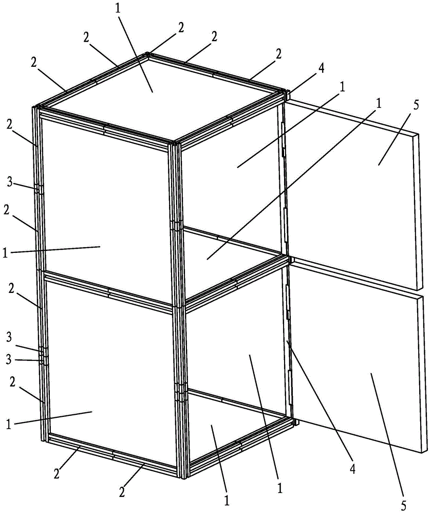
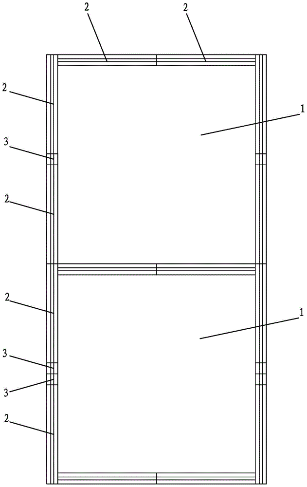
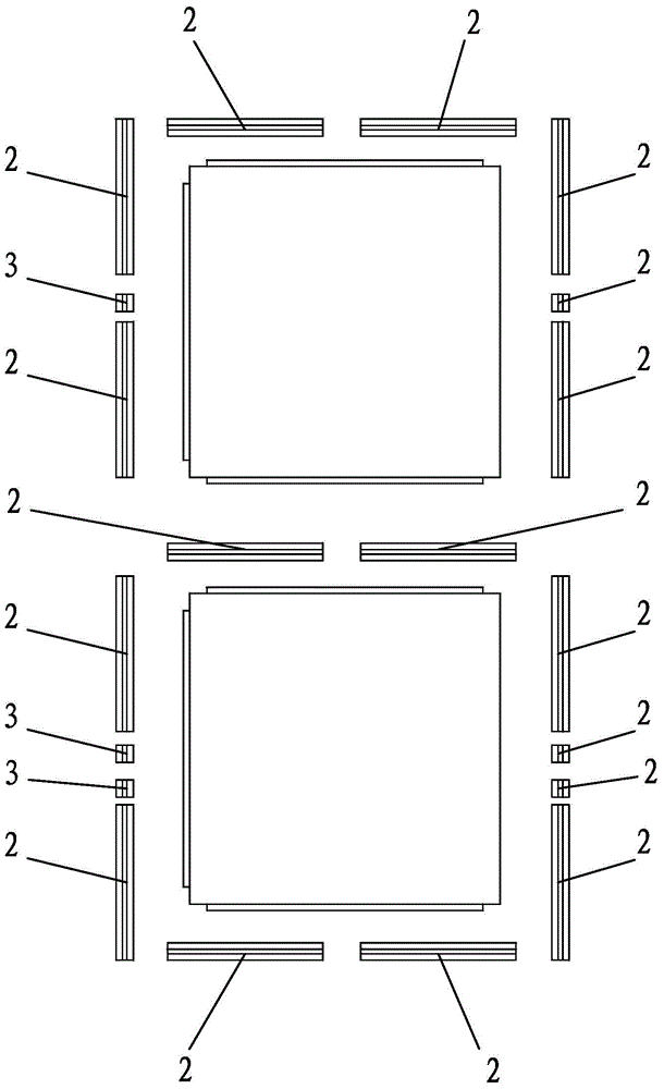
[0027] A further detailed description will be made below in conjunction with the accompanying drawings and embodiments of the present invention:

[0028] Such as Figure 1-14 As shown, a new type of splicing assembly includes a number of first square panels 1, a number of first bar-shaped connectors 2, and a number of second bar-shaped connectors 3, and the square side of the first square panel 1 The length is L and the thickness is D, wherein L>D, the length of the first strip connector 2 And the cross-section is a square with side length D, the length L2=D of the second strip connector 3 and the cross-section is a square with side length D, and there are 3 of the 4 side walls of the first square panel 1 The centers of the side walls are respectively provided with first clamping columns 11 parallel to the long side direction of the side walls, the length of the first clamping columns 11 is not greater than L, and the centers of the four side walls of the first strip connect...


PUM


Abstract

The invention discloses a novel splicing assembly. The novel splicing assembly comprises a plurality of first square surface plates, a plurality of first strip-shaped connecting parts and a plurality of second strip-shaped connecting parts; the sides of the square of each first square surface plate have length L and thickness D, wherein L is more than D; the length of each first strip-shaped connecting part is as shown in the specification, the cross section of each first strip-shaped connecting part is the square with side length D; the length of each second strip-shaped connecting part is L2 which is equal to D, and the cross section of each second strip-shaped connecting part is the square with the wide length D; first clamping columns are respectively arranged in the centers of three of four sidewalls of the first square surface plates; first clamping grooves through which the first clamping columns are clamped inside and outside are respectively formed in the centers of four sidewalls of the first strip-shaped connecting parts; the first clamping grooves are of the length as shown in the specification; second clamping grooves through which the first clamping columns are clamped inside and outside are formed in the centers of the four sidewalls of the second strip-shaped connecting parts; the second clamping grooves are of length D. According to the assembly, few types are provided; the shape, length and thickness are reasonable in design; the matching is convenient; therefore, the splicing is convenient.

Description

[technical field] [0001] The invention relates to a novel splicing component. [Background technique] [0002] The current splicing pieces, such as splicing wooden floors, have a side clamping structure between the floor and the floor. The clamping shaft of the rear installation floor is directly inserted into the slot of the front installation floor. This structure is not firm. When the side is not fixed well or deviates from the horizontal plane due to external force, the rear installation floor is easy to separate from the front installation floor, which is not convenient for actual use, and the general splicing wooden floor structure is spliced ​​on the same plane, which cannot be spliced ​​into a three-dimensional Objects with a sense of space. [0003] Therefore, it is necessary to solve the above problems. [Content of the invention] [0004] The present invention overcomes the deficiencies of the above-mentioned technologies and provides a new type of splicing asse...

Claims


Application Information

Patent Timeline
Patent Type & Authority Applications(China)
IPC IPC(8): A47B47/00
Inventor 王漩
Owner ZHONGSHAN LIFANGTI INTELLIGENT HOUSEHOLD
Why Eureka
Try Eureka