Suction nozzle for vacuum cleaner and cleaning device with suction nozzle

A technology for vacuum cleaners and cleaning heads, which is used in vacuum cleaners, nozzles, cleaning equipment, etc., can solve the problems of increased dust-laden airflow resistance, adverse consequences, and dust cannot be inhaled, and achieves efficient cleaning.

Active Publication Date: 2015-09-09
TIANKE INTELLIGENT TECH CO LTD
View PDF7 Cites 11 Cited by
  • Summary
  • Abstract
  • Description
  • Claims
  • Application Information

AI Technical Summary

Problems solved by technology

[0003] 1. Most of the bristles of the floor brush are arranged outside the concave cavity of the air duct. Pushing the bristles outside the concave cavity of the air duct of the floor brush back and forth can stretch the wool of the carpet, but the dust brushed out by the brush teeth is not in the air. In the concave cavity of the road, so the dust cannot be sucked into the air intake duct; this has basically no effect on the improvement of the cleaning efficiency of the carpet
[0004] 2. The brush teeth of the floor brus

Method used


Image

  • Suction nozzle for vacuum cleaner and cleaning device with suction nozzle
  • Suction nozzle for vacuum cleaner and cleaning device with suction nozzle
  • Suction nozzle for vacuum cleaner and cleaning device with suction nozzle

Examples


Embodiment 1

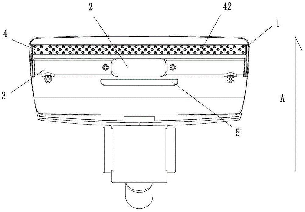
[0032] Figure 1A It is one of the structural schematic diagrams of Embodiment 1 of the suction nozzle for vacuum cleaners of the present invention, as Figure 1A As shown, the present embodiment provides a suction nozzle for a vacuum cleaner, comprising: a casing 1, and an air duct concave cavity is arranged at the bottom of the housing 1, and the air duct concave cavity communicates with the air inlet duct 2, There is a toothless area 3 and a brush tooth area 4 in which the brush teeth 41 are arranged in the concave cavity of the air duct. The brush tooth area 4 includes the brush teeth 41 and the brush tooth base (not shown in the figure). In other words, the brush teeth 41 are arranged in the concave cavity of the air duct. When the brush teeth 41 comb the carpet, there is an air flow, and the dust at the bottom of the carpet combed by the brush teeth 41 is immediately taken away by the air flow in the concave cavity of the air duct. The cleaning efficiency is improved; tak...

Embodiment 2

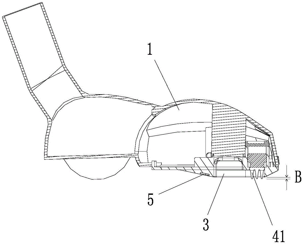
[0043] figure 2 It is a structural schematic diagram of the second embodiment of the suction nozzle for vacuum cleaners of the present invention, as figure 2 As shown, the nozzle structure of the vacuum cleaner in this embodiment is basically the same as that in Embodiment 1, the difference is that:

[0044] In this implementation, the ends of the brush teeth 41 are lower than the side walls of the concave cavity of the air duct, and the height difference C between the ends of the brush teeth 41 and the side walls of the concave cavity of the air duct is lower than 5 mm, and the ends of the brush teeth 41 Being lower than the sidewall of the air duct concave cavity is more conducive to the sealing of the air duct concave cavity, but if the end of the brush teeth 41 is lower than the inner side wall of the air duct concave cavity by more than 5mm, the combing effect of the brush teeth 41 on the carpet is not good. It can sweep out the dust deep in the carpet.

[0045] The w...

Embodiment 3

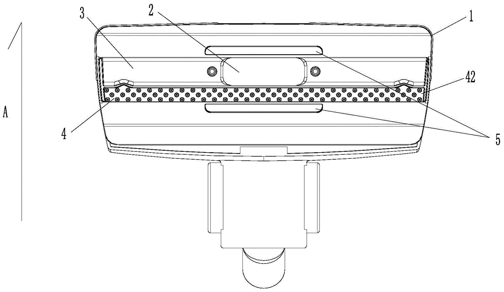
[0047] image 3 It is a structural schematic diagram of the third embodiment of the suction nozzle for vacuum cleaners of the present invention. The structure of the suction nozzles of the vacuum cleaners in this embodiment is basically the same as that of the above two embodiments. The difference is that in this embodiment, The tooth brushing area 4 includes: in addition to the first tooth brushing area 42 arranged on the rear side of the concave cavity of the air duct, the second tooth tooth area 43 is arranged on the left and right sides of the concave cavity of the air duct. Specific as image 3 As shown, the first brush tooth area 42 and the second brush tooth area 43 are extended and connected to form a "U" shape in the concave cavity of the air duct.

[0048] Of course, those skilled in the art can only set the second brush tooth area 43 on either side of the left and right sides of the air duct cavity according to the needs, then the first brush tooth area 42 and the ...


PUM


Abstract

The invention provides a suction nozzle for a vacuum cleaner and a cleaning device with the suction nozzle. The suction nozzle for the vacuum cleaner comprises an outer shell (1), wherein an air flue concave cavity is formed in the bottom of the outer shell (1), communicated with an air inlet pipeline (2) and provided with a tooth-free area (3) and a brushing tooth area (4) where brush teeth (41) are distributed. The cleaning device comprises the suction nozzle for the vacuum cleaner. According to the suction nozzle for the vacuum cleaner and the cleaning device with the suction nozzle, by reasonably distributing the brush teeth in an air flue suction opening, it is guaranteed that the brush teeth can efficiently clean up dust deep in a carpet, and meanwhile influences of the brush teeth on air flow are minimized.

Description

technical field [0001] The invention relates to a suction nozzle for a vacuum cleaner and a cleaning device with the suction nozzle, which belong to the technical field of small household appliance manufacturing. Background technique [0002] The ordinary nozzles currently on the market for vacuum cleaners can only clean the dust on the surface of the carpet due to structural limitations, but cannot effectively clean the dust inside the carpet; generally, the cleaning efficiency is not high. In order to improve the cleaning efficiency of the ground brush, brush teeth are generally arranged at the bottom of the ground brush. In the prior art, there are two kinds of ground brushes as follows: [0003] 1. Most of the bristles of the floor brush are arranged outside the concave cavity of the air duct. Pushing the bristles outside the concave cavity of the air duct of the floor brush back and forth can stretch the wool of the carpet, but the dust brushed out by the brush teeth is...

Claims


Application Information

Patent Timeline
IPC IPC(8): A47L9/02A47L9/06A47L5/12
Inventor 程文杰
Owner TIANKE INTELLIGENT TECH CO LTD
Why Eureka
Try Eureka