Assembly method of phaser lock pin clearance

A phase shifter and gap technology, applied in the field of phase shifter lock pin gap assembly, can solve problems such as abnormal noise at engine cold start, and achieve the effects of reducing processing difficulty, improving assembly production efficiency, and optimizing processing technology.

Active Publication Date: 2015-09-09
ZHEJIANG DAXING TECH
View PDF6 Cites 4 Cited by
  • Summary
  • Abstract
  • Description
  • Claims
  • Application Information

AI Technical Summary

Problems solved by technology

[0003] The purpose of the present invention is to provide a more accurate and practical method for assembling the lock pin gap of the phase shifter, so as to make it more reliable in the performance of unloading and returning, and solve the cold start of the engine caused by the large lock pin gap Noise problem

Method used


Image

  • Assembly method of phaser lock pin clearance
  • Assembly method of phaser lock pin clearance
  • Assembly method of phaser lock pin clearance

Examples


Embodiment Construction

[0012] The present invention will be further described below in conjunction with accompanying drawing.

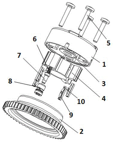
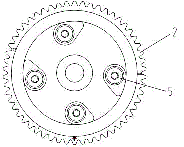
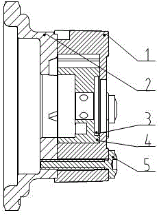
[0013] Such as figure 1 , 2 , 3, 4, and 5, the phase shifter includes a stator 1, a gasket 3, a rotor 4, a lock pin 7, a lock pin sleeve 8, a lock pin spring 6, an oil seal 10, an oil seal spring 9, a sprocket 2 and bolts 5. The phase shifter lock pin gap assembly method, ① The rotor 4, the lock pin 7, the lock pin sleeve 8, the lock pin spring 6, the stator 1, the oil seal 10 and the oil seal spring 9 constitute the stator-rotor assembly, and then the stator-rotor assembly and the sprocket 2 combined and rotated with each other so that the lock pin 7 on the rotor 4 snaps into the lock pin hole on the sprocket 2, and then the bolt 5 is locked into the sprocket 2 with an electric screwdriver so that the stator-rotor assembly and the sprocket 2 will not fall off each other. At this time, the stator-rotor assembly and the sprocket 2 can still rotate with each other; ②Use to...


PUM


Abstract

The invention discloses an assembly method of phaser lock pin clearance, which comprises a stator, a gasket, a rotor, a lock pin, a lock pin sleeve, a lock pin spring, an oil seal, an oil seal spring, a chain wheel and a bolt, wherein the rotor is limited and fixed at first, the stator is then adhered tightly with the rotator, and the chain wheel is finally rotated and adjusted to a required angle, so that lock pin clearance errors caused by size deviation of mutual coordination in part processing are eliminated.

Description

technical field [0001] It is used for the assembly of the phase shifter in the variable valve timing control system (VVT) of the engine. This new method of controlling the clearance of the assembly lock pin can improve the reliability of the phase shifter (VCP)'s opening and returning performance, and also solves the problem of Engine cold start phase shifter abnormal sound problem. Background technique [0002] The phase shifter includes: stator, gasket, rotor, lock pin, lock pin sleeve, lock pin spring, oil seal, oil seal spring, sprocket (lock pin hole and fastening thread are processed on the sprocket) and bolts, etc. composition. When assembling the phase shifter, first press the lock pin, lock pin sleeve and lock pin spring into the rotor on the fixed limit tool to form the rotor assembly, and then put the gasket, rotor assembly, oil seal and oil seal spring into the stator to form the stator-rotor assembly , and finally fix the stator-rotor assembly and the sprocket...

Claims


Application Information

Patent Timeline
Patent Type & Authority Applications(China)
IPC IPC(8): B23P21/00B23P19/10
CPCB23P19/10B23P21/00
Inventor 毕峰源
Owner ZHEJIANG DAXING TECH
Why Eureka
Try Eureka