
Support positioner

A locator and support technology, which is applied in the direction of workpiece clamping devices and manufacturing tools, can solve problems such as tight fit, scratches on the product surface, and difficult control of the tolerance of the lug locator.

Inactive Publication Date: 2015-09-09
JIANGXI HONGDU AVIATION IND GRP
View PDF6 Cites 1 Cited by
  • Summary
  • Abstract
  • Description
  • Claims
  • Application Information

AI Technical Summary

Problems solved by technology

[0005] The support locator adopts the structural form of unilateral fit, which avoids the difficult control of the tolerance of the lug locator caused by the zinc yellow primer sprayed after the parts are processed, and the phenomenon of tight fit during use, and solves the original problem The locator with ear-fork lug structure is often plugged and pulled out, which causes defects such as wear of the locator and scratches on the product surface. At the same time, this matching method facilitates the final removal of the product

Method used


Image

  • Support positioner
  • Support positioner

Examples


Embodiment 1

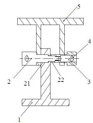
[0011] Such as figure 1 As shown, the support locator is composed of a support 1, a threaded pin 2, a nut 3 and a handle 4; the threaded pin 2 is provided with a first step 21 and a second step 22 whose diameter decreases step by step, and the end is a threaded section ; The support 1 involves a stepped hole, the first-level hole cooperates with the first-level step 21 of the threaded pin 2, the second-level hole cooperates with the second-level step 22 of the threaded pin 2, and the first-level step 21 is matched with the positioning hole of the workpiece 5 to be positioned Cooperate, the nut 3 is provided with an extension section, the outer diameter of the extension section cooperates with the positioning hole of the workpiece 5 to be positioned, the inner hole at the outer end of the extension section cooperates with the secondary step 22 of the threaded pin 2, and the internal thread at the outer end of the extension section matches the threaded pin 2, and the nut 3 is al...

Embodiment 2

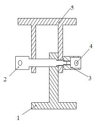
[0014] Such as figure 1 As shown, the support locator is composed of a support 1, a threaded pin 2, a nut 3 and a handle 4; the threaded pin 2 is provided with a first step 21 and a second step 22 whose diameter decreases step by step, and the end is a threaded section ; Relate to the stepped hole on the support 1, the first-level hole cooperates with the first-level step 21 of the threaded pin 2, the second-level hole cooperates with the second-level step 22 of the threaded pin 2, and the large positioning of the first-level step 21 and the workpiece 5 to be positioned Hole fits, the secondary step 22 of threaded pin 2 cooperates with the small positioning hole of positioning workpiece 5, the internal thread of nut 3 cooperates with the threaded section of threaded pin 2, and nut 3 is also provided with handle 4, easy to use.

[0015] For the workpiece 5 to be positioned with unequal holes, the first-level step 21 of the threaded pin 2 passes through the large positioning hol...


PUM


Abstract

The invention provides a support positioner. The support positioner is composed of a support, a threaded pin, a nut and a handle. The threaded pin is provided with a primary step and a secondary step, and the diameter of the primary step and the diameter of the secondary step become smaller gradually. Step holes are formed in the support, the primary hole is matched with the primary step of the threaded pin, the secondary hole is matched with the secondary step of the threaded pin, the handle is arranged on the nut, and a workpiece to be positioned and the supported are fixed together through the nut and the threaded pin. According to the support positioner, the single-edge matching structural form is adopted, the situation that the tolerance of a lug positioner cannot be controlled easily due to the fact that zinc chromate primer is sprayed after a part is machined is avoided, and the phenomenon of inflexible matching in use is avoided.

Description

technical field [0001] The invention relates to a support positioner in the design of an assembly fixture. Its main purpose is to avoid some defects and problems existing in the original support locator used in the assembly fixture. Background technique [0002] Assembly fixtures often involve support-type locators, and support-type locators usually use the matching method of ear fork and ear pieces. After the parts are processed, they need to be sprayed with zinc yellow primer, which makes it difficult to control the tolerance of the lug positioner, and the fit is tight during use. In long-term use, frequent plugging and unplugging will cause defects such as wear of the positioner and scratches on the product surface, and this matching method will bring inconvenience to the final removal of the product. Contents of the invention [0003] Avoid the defects and problems existing in the original support locator, facilitate the positioning and removal of products, optimize ...

Claims


Application Information

Patent Timeline
Patent Type & Authority Applications(China)
IPC IPC(8): B25B11/00
CPCB25B11/00
Inventor 吕冰史庆楠郑雪海
Owner JIANGXI HONGDU AVIATION IND GRP
Learn More