
Method for Operating a Motor Vehicle Brake System, and a Control Device for a Motor Vehicle Brake System

A brake device, parking brake technology, applied in the direction of brake transmission, brake control system, brake, etc.

Active Publication Date: 2015-09-09
ROBERT BOSCH GMBH
View PDF6 Cites 10 Cited by
  • Summary
  • Abstract
  • Description
  • Claims
  • Application Information

AI Technical Summary

Problems solved by technology

However, if the braking system of the motor vehicle fails at least partially, the motor vehicle must therefore be able to be brought safely to a standstill

Method used


Image

  • Method for Operating a Motor Vehicle Brake System, and a Control Device for a Motor Vehicle Brake System
  • Method for Operating a Motor Vehicle Brake System, and a Control Device for a Motor Vehicle Brake System
  • Method for Operating a Motor Vehicle Brake System, and a Control Device for a Motor Vehicle Brake System

Examples


Embodiment Construction

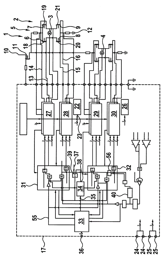
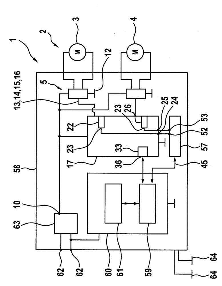
[0029] figure 1 It is a functional diagram of the motor vehicle brake device 1 and briefly shows a circuit diagram of the motor vehicle brake device 1. The motor vehicle brake device 1 has an electronic parking brake 2, which in the embodiment shown here has two actuators 3 and 4. Of course, one actuator 3 is also sufficient; a larger number of actuators 3 or 4 can also be provided. Next, only actuator 3 will be discussed first. The embodiment can also be used for the actuator 4 in a similar manner.

[0030] The actuator 3 can be triggered by means of a switching device 5, which is present as an H-bridge mechanism and has four switches 6, 7, 8 and 9 for this purpose. The switches 6, 7, 8 and 9 are configured as transistors, preferably as MOSFETs. Switches 6 and 7 exist as high-side switches, and switches 8 and 9 exist as low-side switches for actuator 3. In this regard, the switches 6 and 7 are connected to a positive potential on their side facing away from the actuator 3, f...


PUM


Abstract

The disclosure relates to a method for operating a motor vehicle brake system that comprises at least one electronic parking brake having at least one actuator, wherein in the presence of a first switching signal at a switching signal input the actuator is controlled so as to activate the parking brake. It is provided that the switching signal input in a normal operating mode is released so as to apply optional switching signals and in a safety operating mode is set to a second switching signal that is different from the first switching signal so that the process of controlling the actuator so as to activating the parking brake is prevented. The disclosure further relates to a control device for a motor vehicle brake system.

Description

Technical field [0001] The invention relates to a method for operating a brake device of a motor vehicle, which has at least one electronic parking brake with at least one actuator, wherein when a first switching signal is applied to the switching signal input , The actuator is triggered to activate the parking brake. The invention also relates to a controller for a braking device of a motor vehicle. Background technique [0002] Motor vehicle braking devices are used for braking or decelerating motor vehicles. It has an electronic parking brake, which is preferably assigned to an axle of the motor vehicle. The electronic parking brake can be actuated electronically and for this purpose has an actuator which, when triggered, brakes or fixes the axle and therefore the motor vehicle. For this purpose, the actuator acts, for example, on the axle of a motor vehicle. In order to trigger the actuator, a switch signal input terminal is provided, wherein different switch signals can ...

Claims


Application Information

Patent Timeline
Patent Type & Authority Applications(China)
IPC IPC(8): B60T13/74
CPCB60T8/174B60T17/18B60T8/885B60T13/741B60T13/746B60T2270/402B60L50/20B60K25/06
Inventor P.绍特P.雷布霍尔茨-戈尔德曼A.胡特
Owner ROBERT BOSCH GMBH
Learn More