PTAC dehumidification without reheat and without a humidistat

a technology of humidistat and reheating, which is applied in the field of ptac units, can solve the problems of ptac units that are not always suitable for reheating, draw a lot of electric current, and uncomfortable cold rooms, so as to reduce the setpoint temperature, and reduce the speed of the supply air fan

Active Publication Date: 2008-07-03
TRANE INT INC
View PDF38 Cites 35 Cited by
  • Summary
  • Abstract
  • Description
  • Claims
  • Application Information

AI Technical Summary

Benefits of technology

[0011]Another object of some embodiments is to prevent overloading a refrigerant system's electrical system by not running the system's compressor and electric heater concurrently.
[0012]Another object of some embodiments is to provide dehumidification by closing an outside air damper, decreasing the speed of the supply air fan, and effectively lowering the setpoint temperature.
[0013]Another object of some embodiments is to provide dehumidification by automatically closing an outside air damper and decreasing the speed of the supply air fan as the room temperature decreases below a setpoint temperature.
[0014]One or more of these and / or other objects of the invention are provided by a refrigerant system that dehumidifies air without relying on a humidistat and without reheating the air. To reduce the humidity, the system closes an outside air damper, decreases the speed of the supply air fan, and effectively lowers the setpoint temperature.

Problems solved by technology

Cooling alone, however, can make a room uncomfortably cold.
The reheat process is applicable to various refrigerant systems; however reheat is not always suitable for Packaged Terminal Air Conditioners / Heat Pumps, also known as PTAC units.
Even though PTACs often include an electric heater for a heating mode, energizing a refrigerant compressor for cooling / dehumidifying while energizing an electric heater for reheat would draw a lot of electric current.
Such current is not always available due to the often-limited current carrying capacity of the wiring leading to each PTAC unit.
Although heavier wiring could be installed, the cost of the higher gage wires would need to be multiplied by the total number of PTAC units of a particular installation.
For a hotel with numerous PTAC units, the total cost of the wiring is significant.
Another difficulty of providing a PTAC unit with a dehumidifying mode is that typical dehumidification methods involve the use of a humidity sensor.
Although a single humidity sensor may not be that expensive, the total cost can be substantial for installations that include numerous PTAC units.
Although beneficial, the dehumidification that occurs during the extended but limited run time of the fan may not always be sufficient to meet the total dehumidification needs of the comfort zone.
Although such a system is particularly useful during the night when the cooling demand is low, the system is less valuable during periods of high cooling demand.

Method used


Image

  • PTAC dehumidification without reheat and without a humidistat
  • PTAC dehumidification without reheat and without a humidistat
  • PTAC dehumidification without reheat and without a humidistat

Examples


Embodiment Construction

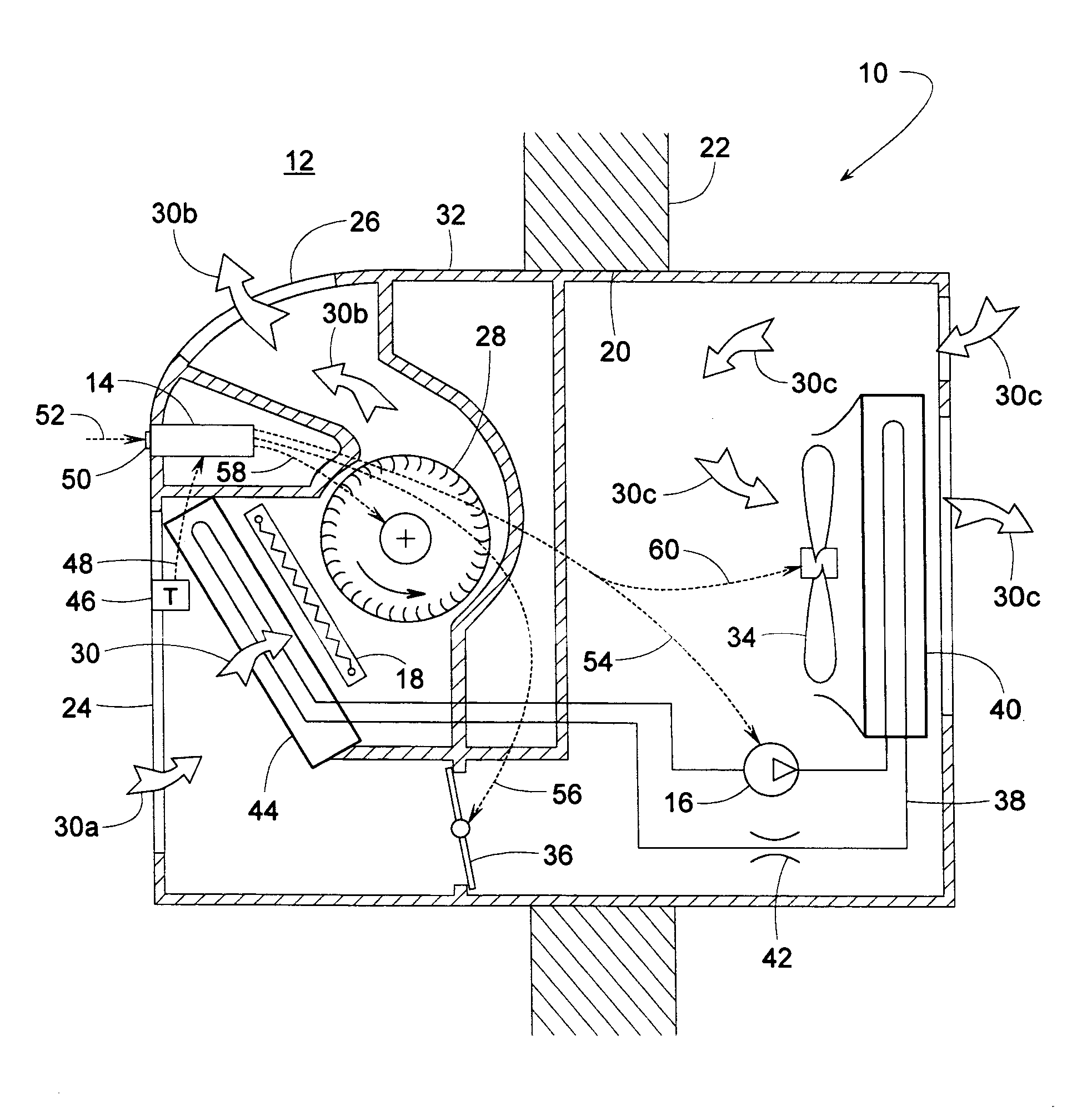
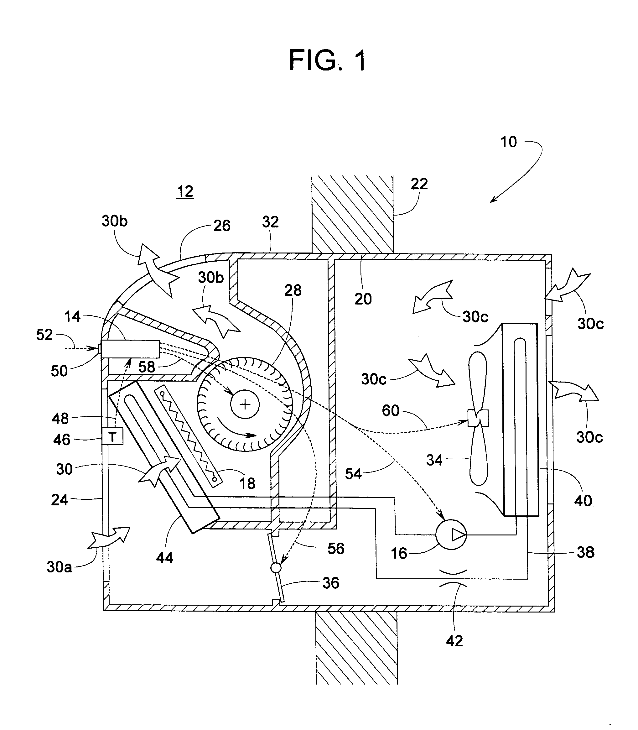
[0020]A refrigerant system 10, schematically shown in FIGS. 1 and 2, can be used for cooling, heating, ventilating or dehumidifying a comfort zone such as a room 12 or other area in a building. System 10 includes a controller 14 that enables the system to provide dehumidification without relying on a humidistat and without having to operate the system's compressor 16 and an optional electric heater 18 at the same time. Although system 10 is illustrated as a PTAC unit, controller 14 can be readily applied to many other types of refrigerant systems as well.

[0021]In a currently preferred embodiment, system 10 can be installed at an opening 20 of a building's exterior wall 22. System 10 has an inlet 24 for receiving recirculated return air 30a from within room 12 and an outlet 26 for discharging conditioned supply air 30b back into room 12. A supply air fan 28 disposed within a housing 32 moves the air from inlet 24 to outlet 26. Housing 32 also contains an outdoor fan 34, a fresh air d...


PUM


Abstract

A refrigerant system includes a controller that enables the system to dehumidify the air in a room without relying on a humidistat and without having to operate the system's compressor and electric heater at the same time. To dehumidify the air, the system's compressor, supply air fan, and outside air damper are controlled in a manner similar to other systems operating in a cooling mode when the room temperature is above a certain setpoint temperature. When the room temperature falls below the setpoint, however, the operation changes significantly. The controller closes the outside air damper, decreases the speed of the fan, and continues operating in this manner until the room temperature decreases to a subcooling temperature limit. The subcooling temperature limit is less than a predetermined limit that is used during the system's normal cooling mode.

Description

BACKGROUND OF THE INVENTION[0001]1. Field of the Invention[0002]The subject invention generally pertains to almost any type of HVAC refrigerant system but particularly to PTAC units such as those commonly used for hotel rooms. The invention more specifically pertains to a method of providing such systems with a dehumidification mode without using a reheat coil or relying on a humidistat.[0003]2. Description of Related Art[0004]Refrigerant systems are widely used for heating, cooling and dehumidification of a comfort zone such as a room or other area of a building. Dehumidifying air may simply involve cooling the air below its dew point. Cooling alone, however, can make a room uncomfortably cold. Thus, a heater is sometimes activated to offset the cooling effect, whereby the air can be dehumidified without changing the temperature of the room. The use of a heater while dehumidifying by cooling is known as a reheat process.[0005]The reheat process is applicable to various refrigerant ...

Claims


Application Information

Patent Timeline
Patent Type & Authority Applications(United States)
IPC IPC(8): F24F3/14G05D23/00F25B49/02
CPCF24F1/027F24F3/1405F24F2011/0002F25B2400/01F25B49/02F25B2313/0293F25B13/00
Inventor ZHOU, QIANGHUAJOHNSON, TEDD P.HYFTE, TODD A. VAN
Owner TRANE INT INC
Why Eureka
Try Eureka