Load monitoring system

a monitoring system and load technology, applied in the field of load monitoring systems, can solve the problems of imposing limitations on the transportation of loads by trucks, dimensional and weight limitations, and lack of information

Inactive Publication Date: 2011-08-11
HAKKINEN SEPPO
View PDF4 Cites 33 Cited by
  • Summary
  • Abstract
  • Description
  • Claims
  • Application Information

AI Technical Summary

Benefits of technology

[0058]The control output might be used for stopping the loading cycle. For example, this may be done in response to the mass of the payload module exceeding a threshold value. This value may be set such as to prevent dangerous overloading of the vehicle.
[0059]The control output might be used to disable movement of the vehicle. Thus, for example, the driver can be prevented from driving away the vehicle if the mass of the payload module is producing an overload, and / or if the weight distribution is too far off centre and produces an off-centre centre of gravity of the payload module which could cause a stability or safety problem if the vehicle were to drive off.

Problems solved by technology

National authorities impose limitations on the transportation of loads by trucks.
Specifically, dimensional and weight limitations are imposed.
However, in cross-country travel or when travelling on unsurfaced roads, electronic safety devices are usually switched off because the truck usually has big wheel or tyre dimensions and carries a large mass and will undergo long suspension travel when travelling on the unsurfaced road or when travelling cross-country.
This lack of information is a particular problem with closed containers, because the driver cannot even see the load contained within the container.
However, in spite of this responsibility, the driver has no way of determining how safe the load is that is being carried in or on the demountable payload module.
A demountable payload module is more complex because it moves horizontally and vertically relative to the vehicle chassis.
However, in order to determine the weight of the load from the measurement at the single position, it is necessary to assume that the load is evenly distributed in the container, and often this will not be the case.

Method used


Image

  • Load monitoring system
  • Load monitoring system
  • Load monitoring system

Examples


Embodiment Construction

[0078]The preferred embodiments are only examples and should not be taken to be limiting of the scope of the invention.

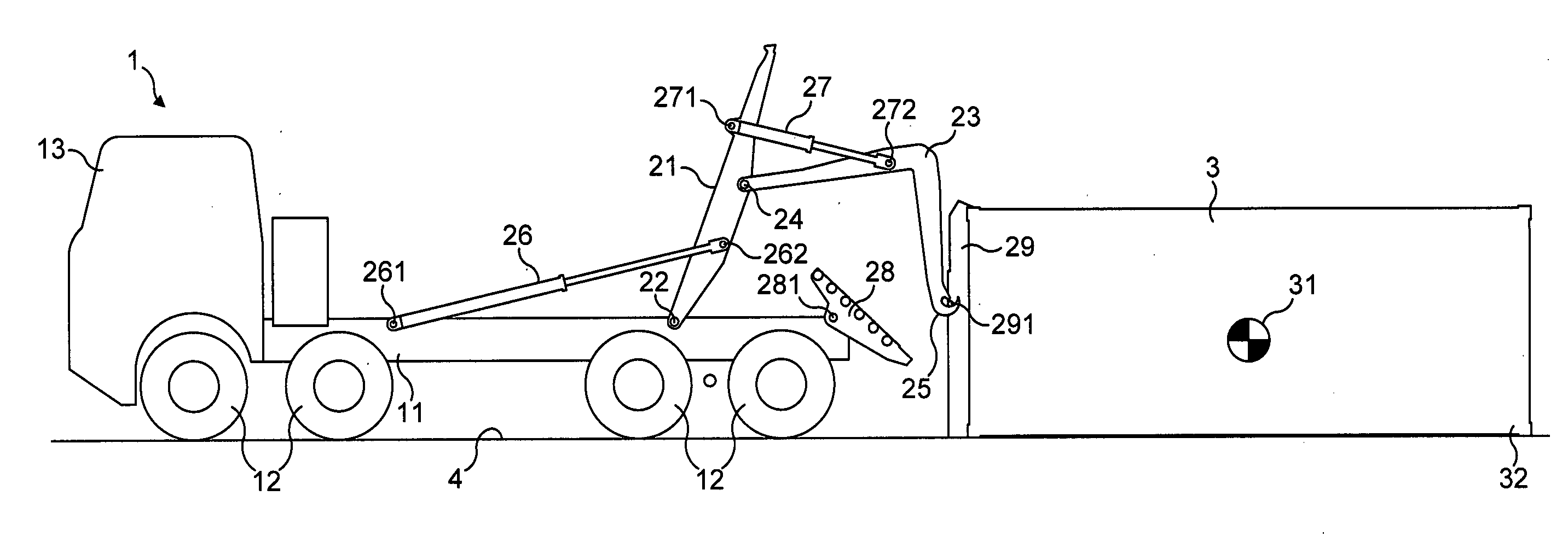
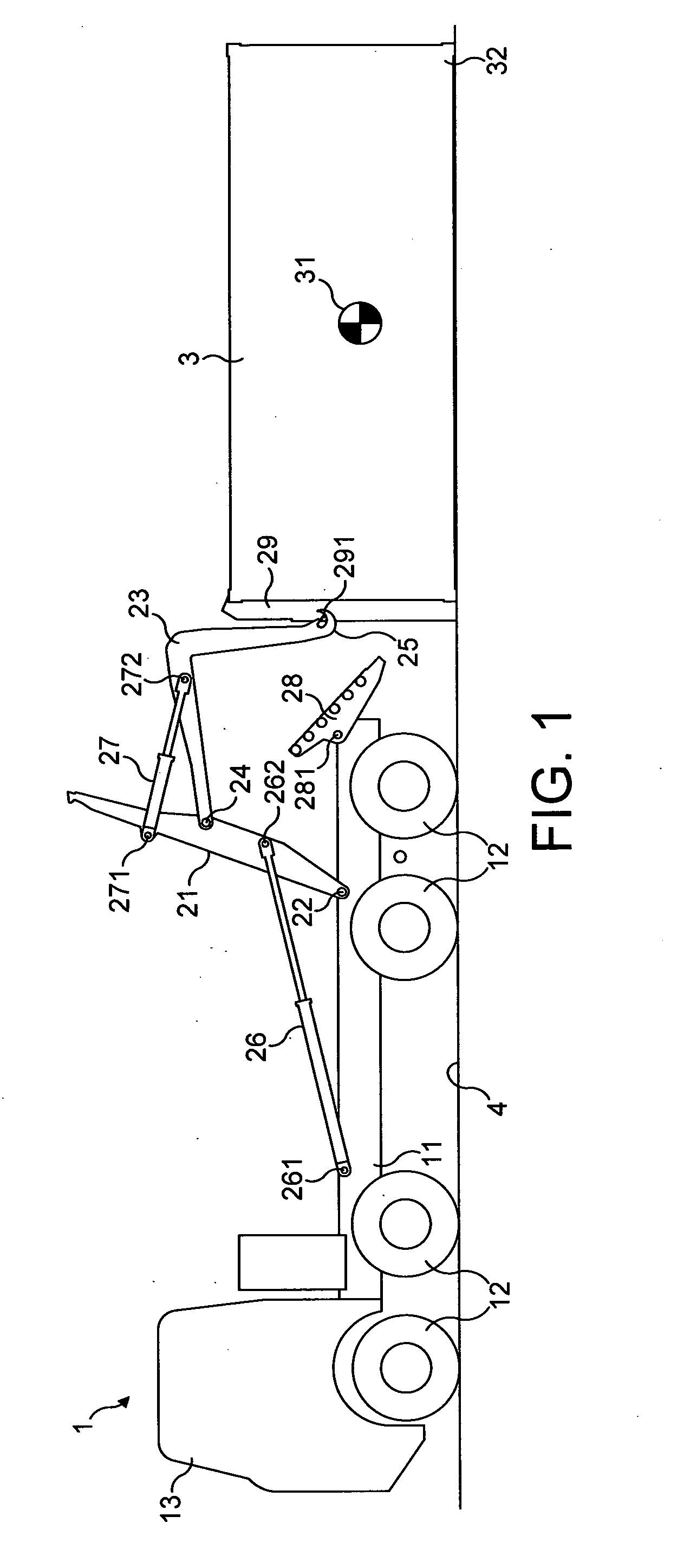
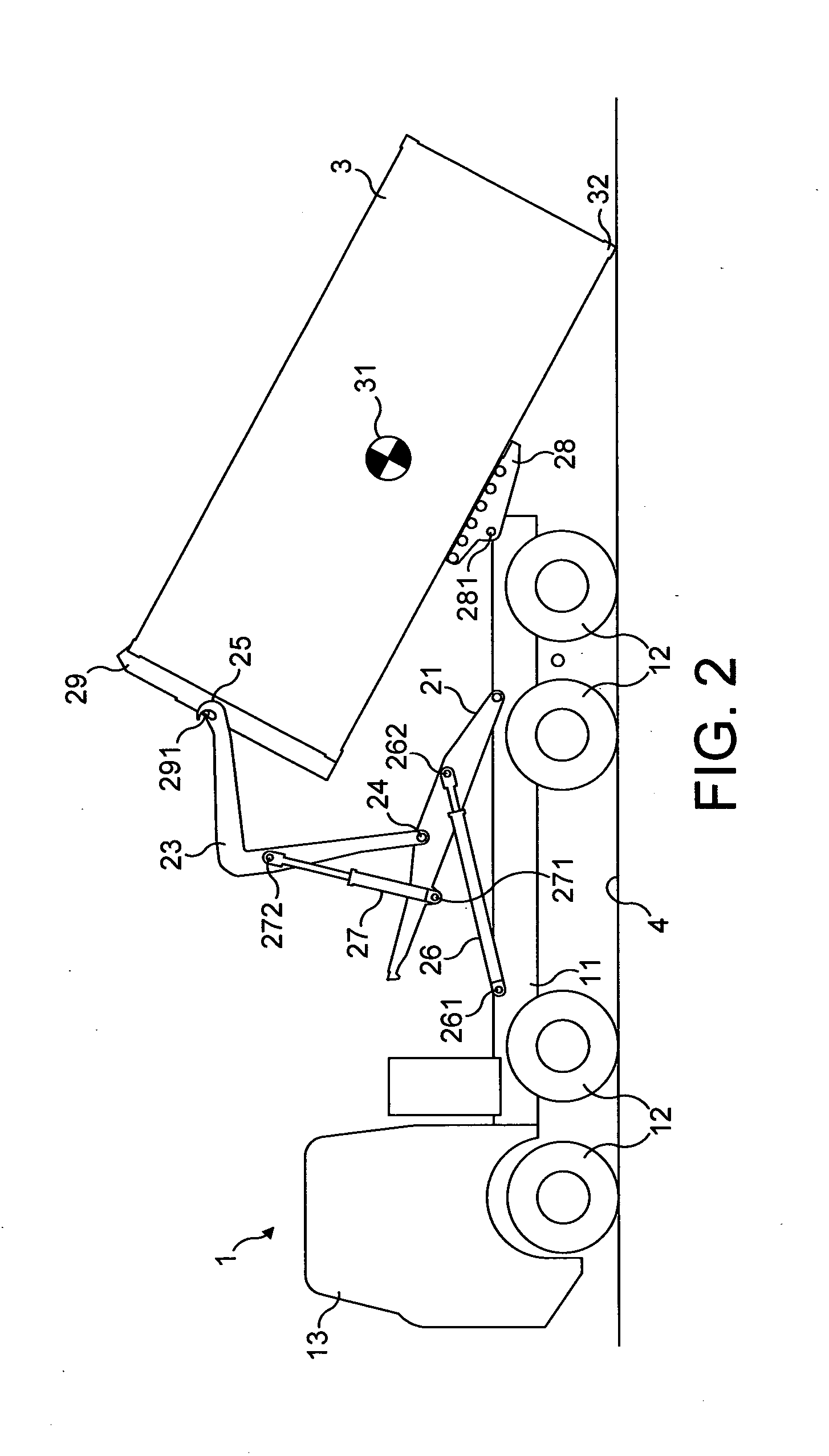
[0079]Referring to FIGS. 1 to 4, there is shown the loading cycle of a load handling system from initial pick-up (FIG. 1) through to completion of the loading (FIG. 4).

[0080]A vehicle (1) comprises a chassis (11) supported on four sets of wheels (12) mounted on respective axles. A cab (13) is mounted at the front end of the chassis (11).

[0081]A load handling system (2) is of the hook-lift type, and specifically is of the tilting hook arm type. It comprises a middle frame (21) which is connected via a pivot (22) to the chassis (11). A hook arm (23) is connected via a pivot (24) to the middle frame (21). The hook arm (23) incorporates a hook (25) at its free end.

[0082]A pair of middle frame cylinders (26) are each positioned on a respective side of the middle frame (21) and are connected via pivots (261) to the chassis (11) and via pivots (262) to the middle frame (21...


PUM


Abstract

A load monitoring system (5) is used to monitor the loading of a vehicle (1) by a load handling system (2) which is movable through a loading cycle to load a payload module (3) onto the vehicle (1) from the ground (4). The load monitoring system (5) comprises sensors (53) for sensing positional information and loading force information of the load handling system (2) at multiple positions during the loading cycle. A data processor (54) uses this information to calculate the mass of the payload module (3) and the position of the centre of gravity (31) of the payload module (3).

Description

Field of the Invention[0001]The present invention relates to a load monitoring system for use in monitoring the loading of a vehicle, such as a military truck, by a load handling system which is carried by the vehicle. The invention is particularly, but not exclusively, applicable to a load handling system which is of the hook-lift type, wherein the load handling system is used to load a demountable payload module such as an ISO container or a flatrack.BACKGROUND OF THE INVENTION[0002]National authorities impose limitations on the transportation of loads by trucks. Specifically, dimensional and weight limitations are imposed.[0003]For example, a maximum overall weight of the vehicle (gross vehicle weight—GVW) is often specified and is generally dependent on how many axles the vehicle has. The load on an axle is limited in order to protect the road surface and bridges.[0004]Safety devices are employed in modern trucks to protect the truck from overturning or becoming uncontrollable. ...

Claims


Application Information

Patent Timeline
Patent Type & Authority Applications(United States)
IPC IPC(8): G06F19/00
CPCB60P1/6463G01M1/122G01G23/3728G01G19/12G01G19/08G01G19/14
Inventor HAKKINEN, SEPPO
Owner HAKKINEN SEPPO
Why Eureka
Try Eureka