
Method and network nodes for reporting at least one dropped-out connection path withing a communication network

a communication network and connection path technology, applied in the field of communication network dropout reporting methods and network nodes, can solve the problems of requiring a drastic modification of the current network node or router implementation, and achieve the effect of cyclical transmission and very rapid transfer

Inactive Publication Date: 2007-05-17
NOKIA SIEMENS NETWORKS GMBH & CO KG
View PDF7 Cites 35 Cited by
  • Summary
  • Abstract
  • Description
  • Claims
  • Application Information

AI Technical Summary

Benefits of technology

[0031] An object of the present invention is now to operate a communication network consisting of a number of network nodes so that if joker links are used and if connecting links drop out, routing loops will be avoided.
[0033] The advantage of invention lies in the fact that, when joker links are used and two connecting links or connections drop out, a circulation of packets is prevented and thus overloading of connecting links or connections and network nodes is avoided. The invention first specifies a method with which automatically and without the intervention of a central unit, loops which could arise if joker links are used and connection paths fail, are detected and interrupted.
[0035] In an advantageous embodiment of the invention a message is transmitted at the start of a disruption and at the end of a disruption from a network node to its neighboring network node. This has the advantage that only a minimum number of messages are used for reporting disruptions.
[0036] In another advantageous embodiment of the invention what are referred to as keep-alive messages are expanded and used for reporting disruptions. This has the advantage that a known message for reporting disruptions is used and in addition is transferred very quickly and cyclically.

Problems solved by technology

Even if one could formulate technical solutions to this problem these are still very complex and demand a drastic modification of the current network node or router Implementations.

Method used


Image

  • Method and network nodes for reporting at least one dropped-out connection path withing a communication network

Examples


Embodiment Construction

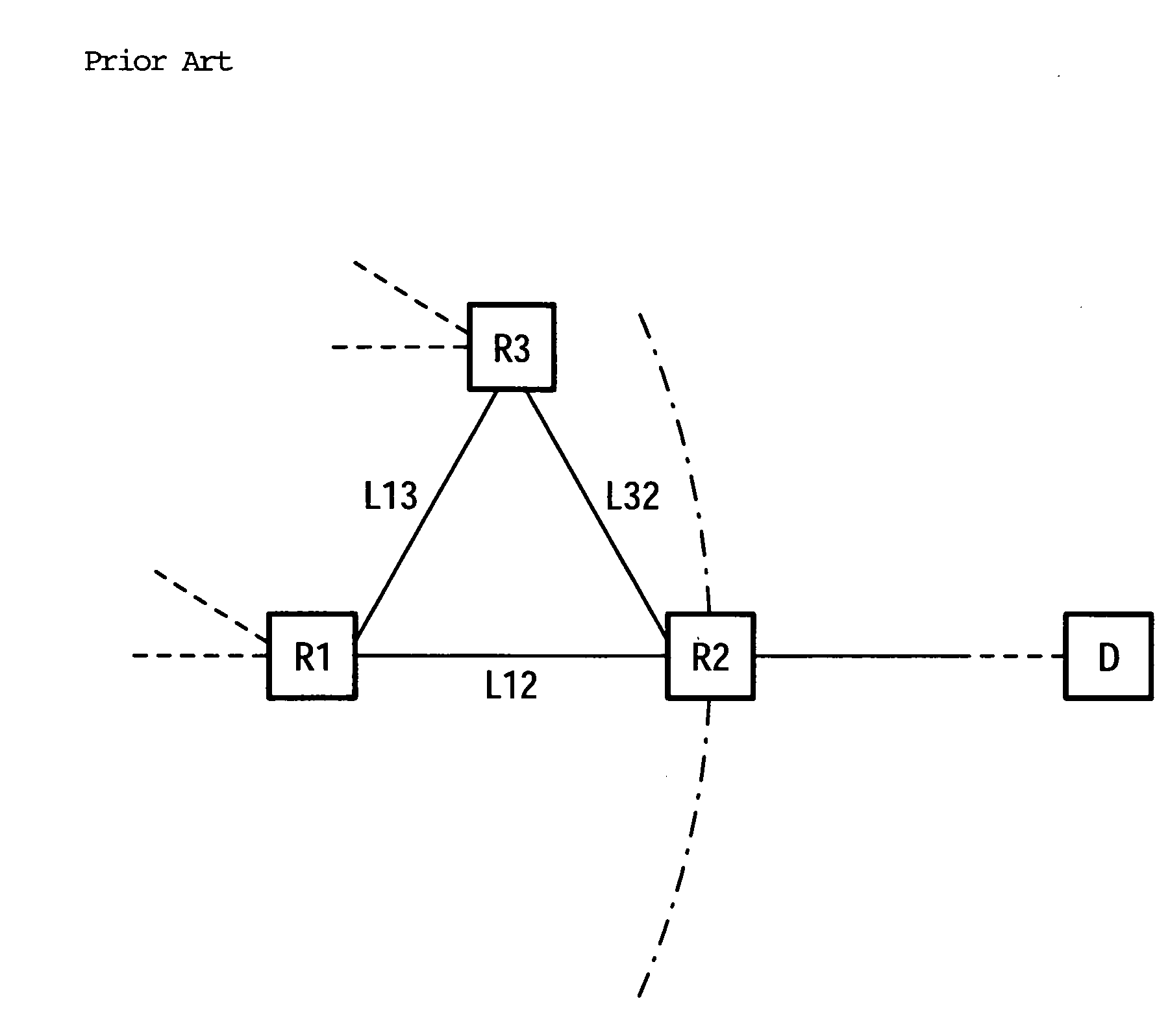
[0039]FIG. 1 shows the arrangement of a part of a packet switching data network already described in the introduction. Using the method of operation describe there as its starting point, what is referred to as a one-hop loop occurs if two routers adjoining the joker link, in the example network nodes R1 and R3, each detect a disruption or an error in the direction of the network node R2 and autonomously activate the joker link in their direction.

[0040] With the present invention each of the two network nodes R1 and R3 is informed when the network node at the other end of the joker link, in the example R3 or R1, can no longer reach the network node R2.

[0041] If the connection L12 is disrupted or has dropped out the network node R1, as described at the start, uses its joker link to the network node R3 to send data packets to the destination D or to the network node R2. In addition, in accordance with the invention, the network node R1 now immediately informs the network node R3 abou...


PUM


Abstract

A network node in the communication network is a target network node, connected by a first communication path with at least one first and one second network node, connected to each other by means of a further communication path. A routing table is held in each network node. The direct communication path from the first network node to the target network node is entered in the routing table of the first network node as the primary routing path and the path leading from the first network node to the second network node and then to the target network node is entered as the reserve routing path. An analogous entry is made in the routing table of the second network node. The relevant reserve routing path is only used on disruption of the primary routing path. A disruption in the primary communication path, provided between the first network node and the target network node is reported by the first network node, by means of a message sent to the second network node. This controls the second network node such that, on a drop-out of the primary connection path thereof to the target network node, a transmission of data packets to the target network node by means of the reverse routing path, leading from the second network node to the target network node via the first network node, is prevented.

Description

CROSS REFERENCE TO RELATED APPLICATIONS [0001] This application is the US National Stage of International Application No. PCT / EP2004 / 051540, filed Jul. 19, 2004 and claims the benefit thereof. The International Application claims the benefits of German application No. 10334104.8 DE filed Jul. 25, 2003, both of the applications are incorporated by reference herein in their entirety.FIELD OF INVENTION [0002] The invention relates to a method and a network node for reporting a dropped-out connection path within a communication network. BACKGROUND OF INVENTION [0003] Different routing methods are used for routing or transmission of data packets with a destination address, such as Internet Protocol packets, abbreviated to IP packets, or Protocol Data Units, abbreviated to PDUs, from a transmitter to a receiver in a packet switching data network featuring a number of network nodes, for example routers, switches or gateways, such as Internet Protocol networks, abbreviated to IP networks or...

Claims


Application Information

Patent Timeline
Patent Type & Authority Applications(United States)
IPC IPC(8): H04L12/56
CPCH04L45/00H04L45/02H04L45/22H04L45/28
Inventor SCHOLLMEIER, GEROWINKLER, CHRISTIAN
Owner NOKIA SIEMENS NETWORKS GMBH & CO KG
Learn More