Direction controllable grouting device and method suitable for prefabricated hollow piles

A technology of grouting device and hollow pile, which is applied in the direction of sheet pile wall, building, and foundation structure engineering. high intensity effect

Active Publication Date: 2017-03-08
山东省建筑科学研究院有限公司 +1
View PDF12 Cites 0 Cited by
  • Summary
  • Abstract
  • Description
  • Claims
  • Application Information

AI Technical Summary

Problems solved by technology

This device can only realize pile end grouting, and cannot carry out combined grouting at the bottom and side of piles
[0003] After a comprehensive analysis of the above post-grouting devices and methods, there are mainly the following deficiencies: 1. The post-grouting device or post-grouting prefabricated hollow pile has no check valve, and the grouting direction cannot be controlled according to the grouting pressure, that is, the direction-controllable injection cannot be realized. 2. The pipeline of the post-grouting device is complicated or protrudes outside the prefabricated hollow pile, which makes the construction difficult and difficult to guarantee the construction quality; 3. Most of the post-grouting devices can only realize the post-grouting of the pile side or the bottom of the pile alone Post-grouting, the effect of improving the bearing performance of pile foundation is limited; 4. The post-grouting device is only suitable for a specific pile type, with a single function, and cannot be flexibly selected for pile bottom, pile side, or pile bottom and pile side joint grouting according to needs ;5. Part of the grouting device is difficult to manufacture, the structure is relatively fragile, and the reliability of the structure is reduced after construction, and it is difficult to guarantee the grouting effect; 6. The post-grouting prefabricated hollow pile needs to be customized and processed by the factory, and the production cost is relatively high

Method used


Image

  • Direction controllable grouting device and method suitable for prefabricated hollow piles
  • Direction controllable grouting device and method suitable for prefabricated hollow piles
  • Direction controllable grouting device and method suitable for prefabricated hollow piles

Examples


Embodiment 1

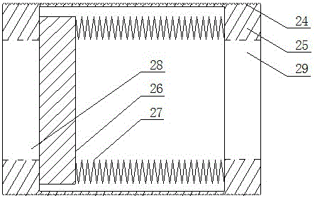
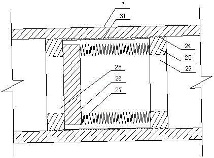
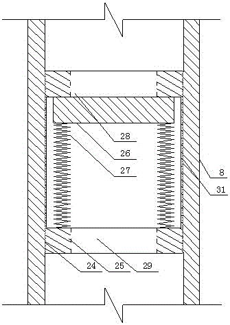
[0028] Embodiment 1: as Figure 4~5 As shown, a direction-controllable grouting device suitable for prefabricated hollow piles includes a base 4 formed by one-time pouring of reinforced concrete. The upper part of the base 4 is a cylindrical platform 22, and an upward The extended cylindrical guide boss 21, the bottom of the base 4 is a rounded platform 23; the inside of the base 4 is provided with the main grouting channel 6, the first branch 7, the second branch 8, the main grouting channel 6 The lower part communicates with the first branch 7 and the second branch 8 at the same time; the second branch 8 is located directly below the main grouting channel 6 and is directly connected with the main grouting channel 6. A diameter smaller than The reducing pipe 15 of the second branch 8. Also be provided with pile side grout outlet 10 and pile bottom grout outlet 13 on base 4, and the pile bottom grouting channel 11 that communicates with pile bottom grout outlet 13, the pile s...

Embodiment 2

[0037] Embodiment 2: The similarities between this embodiment and Embodiment 1 will not be repeated. The difference is a direction-controllable grouting method suitable for prefabricated hollow piles, which uses direction-controllable grouting suitable for prefabricated hollow piles. The device specifically includes the following steps: inserting the guide boss of the base into the inner cavity of the prefabricated hollow pile, adopting the single-pipe method for grouting, and adjusting the first branch, the second branch, the pile bottom grouting channel, and the pile side grouting channel Combined with the different stiffness coefficient k of the inner spring of the check valve at the pile side and the check valve at the bottom of the pile, grouting at the pile side first and at the bottom of the pile, grouting at the pile bottom first and then the pile side, grouting at the pile side alone or Individual pile bottom grouting.

[0038] The grouting device and the bottom of th...

Embodiment 3

[0042] Embodiment 3: The similarities between this embodiment and Embodiment 2 will not be repeated, and the differences are as follows Figure 17 As shown, all the pile bottom grouting channels 11 are connected to one first branch 7, only one pile bottom check valve 3 is needed, which reduces the cost of the grouting device. The structure can be constructed by first pile side grouting→pile bottom grouting.


PUM


Abstract

A direction-controllable grouting device and method applicable to a prefabricated hollow pile comprises a base formed by pouring of reinforced concrete. The upper portion of the base is a cylindrical stylobate. A cylindrical guiding boss extending upwards is arranged on the top surface of the stylobate. The lower portion of the base is a reverse stylobate. A main grouting channel, a first branch and a second branch are arranged in the base, wherein the lower portion of the main grouting channel is respectively communicated with the first branch and the second branch, the second branch is located under the main grouting channel and directly communicated with the main grouting channel in an isometric mode, and a reducing pipe whose diameter is smaller than the second branch is arranged below the second branch. A pile side pulp outlet, a pile bottom pulp outlet, a pile bottom grouting channel communicated with the pipe bottom pulp outlet and a pile side grouting channel communicated with the pile side pulp outlet are further arranged on the base. The first branch is communicated with the pile bottom grouting channel, the second branch is communicated with the pile side grouting channel, or the first branch is communicated with the pile side grouting channel and the second branch is communicated with the pile bottom grouting channel.

Description

technical field [0001] The invention relates to the technical field of post-grouting of prefabricated hollow piles in construction engineering, in particular to a direction-controllable grouting device and method suitable for prefabricated hollow piles. Background technique [0002] Prefabricated hollow piles have the advantages of reliable pile quality, fast construction speed, low cost per unit bearing capacity, and civilized construction sites, and are generally welcomed by construction and design units. However, some problems have also been encountered while prefabricated hollow piles are flourishing. Due to the smooth surface of some prefabricated hollow piles, the pile side frictional resistance cannot be effectively exerted; some prefabricated hollow piles cannot reach the design value because the pile ends are in soft soil; Improper use will lead to quality problems such as cracks, tilting or broken piles in the pile body. In view of the above-mentioned problems of ...

Claims


Application Information

Patent Timeline
Patent Type & Authority Patents(China)
IPC IPC(8): E02D5/62E02D5/72E02D15/04
Inventor 卜发东宋义仲程海涛朱锋李文洲米春荣薛庆峰周洋房启林李建明孟炎付强王志韩国梁张化峰陈钰
Owner 山东省建筑科学研究院有限公司
Why Eureka
Try Eureka