
A bolt for electric power

A technology of anchor bolts and electric power, which is applied in construction, sheet pile walls, foundation structure engineering, etc., can solve problems such as inconvenient anchor bolts, and achieve the effects of convenient electric power construction, simple structure, and convenient use

Inactive Publication Date: 2016-07-06
国网山东济南市历城区供电公司 +1
View PDF5 Cites 0 Cited by
  • Summary
  • Abstract
  • Description
  • Claims
  • Application Information

AI Technical Summary

Problems solved by technology

[0003] The purpose of the present invention is to provide a bolt for electric power, which is used to solve the problem that it is inconvenient to put the bolt into the bottomed hole

Method used


Image

  • A bolt for electric power
  • A bolt for electric power
  • A bolt for electric power

Examples


Embodiment Construction

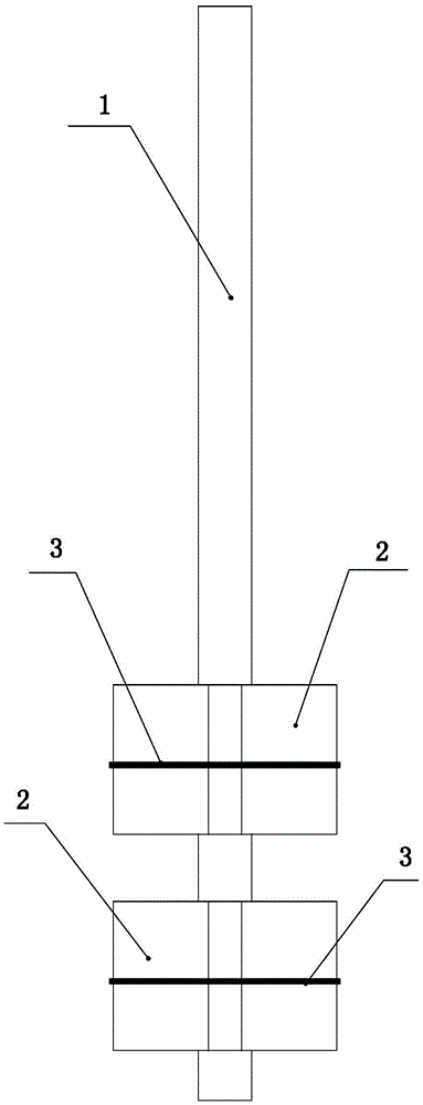
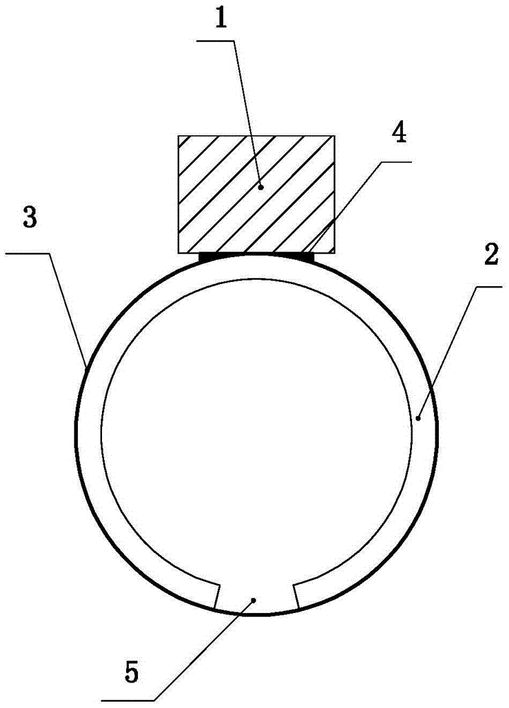
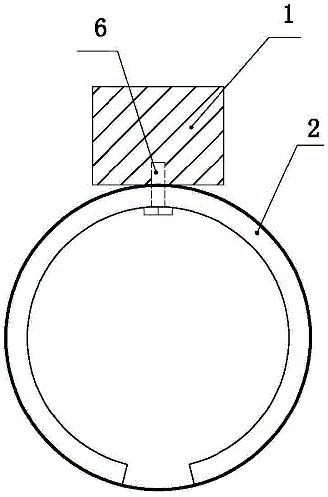
[0017] Such as Figure 1 to Figure 9 As shown, the present invention mainly includes a rod body 1, a horizontal plate 2 and a rope 3, and various embodiments of the present invention will be described below in conjunction with the accompanying drawings.

[0018] Such as figure 1 , figure 2 As shown, the first embodiment of the present invention includes a rod body 1, a horizontal plate 2 and a rope 3, the rod body 1 is a square metal rod, and at least one horizontal plate 2 is fixed at the bottom of the rod body by welding 4, and the horizontal plate 2 is a square metal plate , the middle part of the horizontal plate is welded and fixed with the rod body. The two ends of the horizontal plate are close to but not in contact with each other, and the horizontal plate is bent into an arc shape, and a gap 5 is provided between the two ends of the horizontal plate. In order to keep the horizontal plate in an arc-shaped state, a rope 3 is bound on the horizontal plate. Like this,...


PUM


Abstract

The invention provides an anchor rod used for electric power, used to solve a problem that placing the anchor rod in a bottom expanding aperture is not convenient. The anchor rod comprises a rod body, and is characterized in that the lower part of the rod body is provided with a plurality of horizontal plates, the horizontal plates are bundled by ropes, under the action of the ropes, the horizontal plates maintain an arc state, the lateral dimension of the arc-shaped horizontal plate is smaller than the diameter of a straight hole in foundation, and two ends of the horizontal plate is provided with a gap. When the rope is cut off, the horizontal plate is unfolded and is in the bottom expanding aperture under the straight hole, and the lateral dimension of the horizontal plate in the unfolded state is larger than the diameter of the straight hole. Since after the horizontal plate is bended to the arc shape, the lateral dimension of the horizontal plate is smaller than the diameter of the straight hole, the rod body can extend into the bottom expanding aperture conveniently. The horizontal plate is bundled by the rope, and after the rope is cut off by a blade, the horizontal plate is unfolded, and then the lateral dimension of the horizontal plate is larger than the diameter of the straight hole. The anchor rod is simple in structure and convenient in use, and can conveniently extend into the straight hole. The anchor rod is convenient for electric power construction.

Description

technical field [0001] The invention relates to the technical field of electric power construction, in particular to a bolt for electric power. Background technique [0002] In electric power construction, the existing anchor rod structure is: the anchor rod is fixed to the foot plate of the iron tower of the power transmission line by the anchor bolt, the anchor rod is located in the straight hole below the tower foot plate, and the bottom of the straight hole is connected with an enlarged bottom hole , the fixing device at the bottom of the anchor rod is located in the reamed hole. The fixing device is a rectangular steel plate. When the anchor rod is placed in the reamed hole, since the transverse dimension of the steel plate is smaller than the diameter of the reamed hole and larger than the diameter of the straight hole, when the anchor rod is placed in the reamed hole, there is Put in the inconvenient question. Contents of the invention [0003] The purpose of the ...

Claims


Application Information

Patent Timeline
Patent Type & Authority Patents(China)
IPC IPC(8): E02D5/80
Inventor 孙毅
Owner 国网山东济南市历城区供电公司
Learn More