
Improved anchoring part device

An anchor and improved technology, which is applied in covering/lining, building, building structure, etc., can solve the problems of damaged decorative panels, small installation stress area, and insufficient pulling force, so as to ensure the effect of heat preservation and heat insulation , Guarantee the anchoring strength and block the effect of hot and cold bridges

Inactive Publication Date: 2015-09-09
ZHEJIANG XINRUIMING DECORATIVE MATERIAL
View PDF6 Cites 2 Cited by
  • Summary
  • Abstract
  • Description
  • Claims
  • Application Information

AI Technical Summary

Problems solved by technology

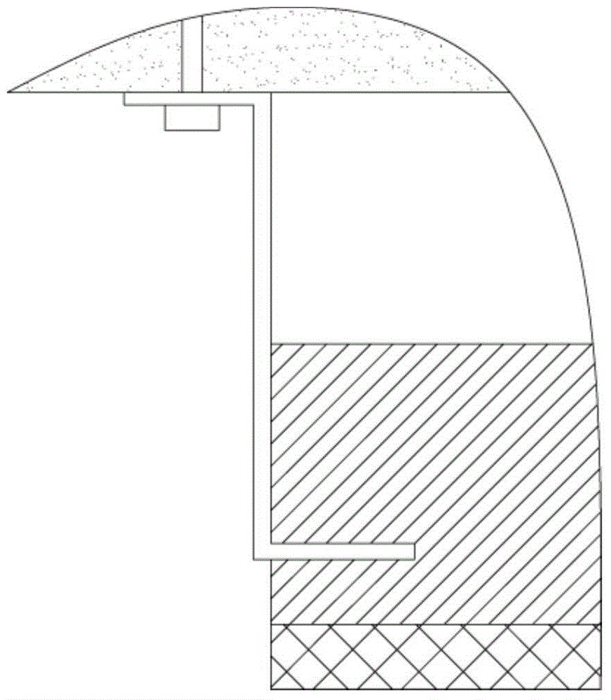
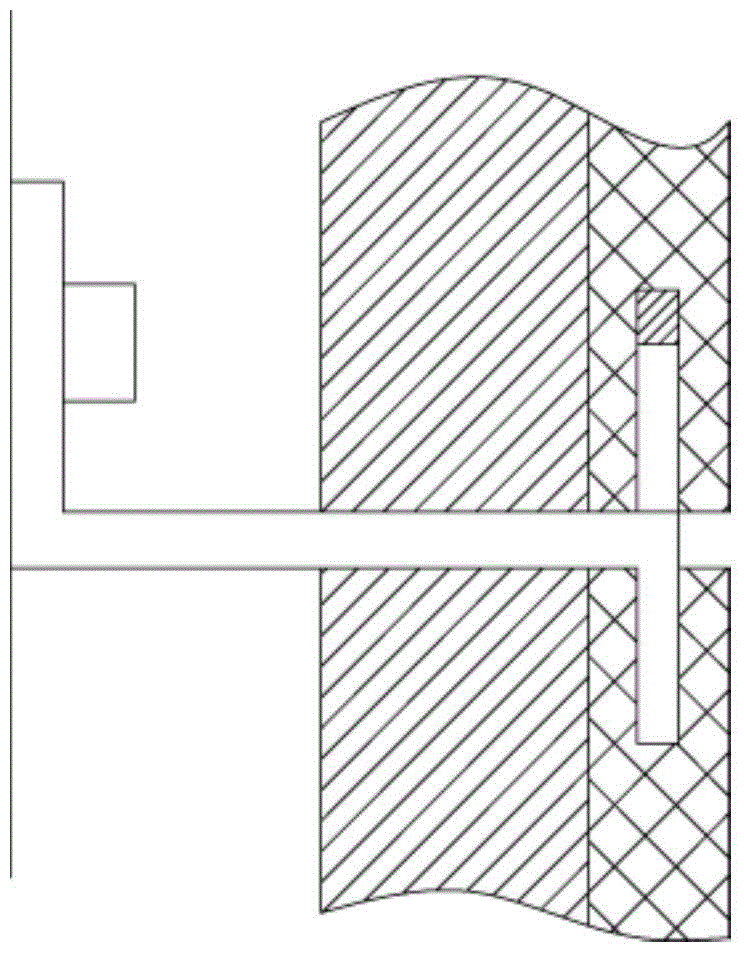
[0002] Existing wall panel anchors consist of a Z-shaped connector and a butterfly fastener, such as figure 1 and figure 2 As shown, the connection is fixed on the wall by a Z-shaped connector and a butterfly-shaped fastener. The two Z-shaped connectors are on both sides of the insulation board, and the butterfly-shaped fastener is fixed on the upper part of the insulation board. , the butterfly fastener has upward-bending and downward-bending protrusions, and the protrusions are inserted into the corresponding sockets on the insulation board, which cannot adjust the distance between the upper insulation board and the lower insulation board. , at the same time, the Z-shaped connector can only fix the insulation layer of the insulation board, forming a cold and heat bridge, and the decorative panel is not effectively anchored, posing a safety hazard
Butterfly fasteners are fixed on the side slots on the decorative panel of the thermal insulation board. The installation stress area is small, and the pulling force is not enough. At the same time, when installing, the panel and the fastener are directly connected, and it is easy for the decorative panel to be damaged due to careless operation of the worker. It is damaged, and installation is troublesome, requiring two people to cooperate, and the installation efficiency is low

Method used


Image

  • Improved anchoring part device
  • Improved anchoring part device
  • Improved anchoring part device

Examples


Embodiment Construction

[0020] The technology of the present invention will be described in detail below in conjunction with the accompanying drawings and specific preferred embodiments, so that the advantages and characteristics of the technology of the present invention can be more easily understood by those skilled in the art. These embodiments are for illustrative purposes only and are not intended to The scope of the present invention is defined.

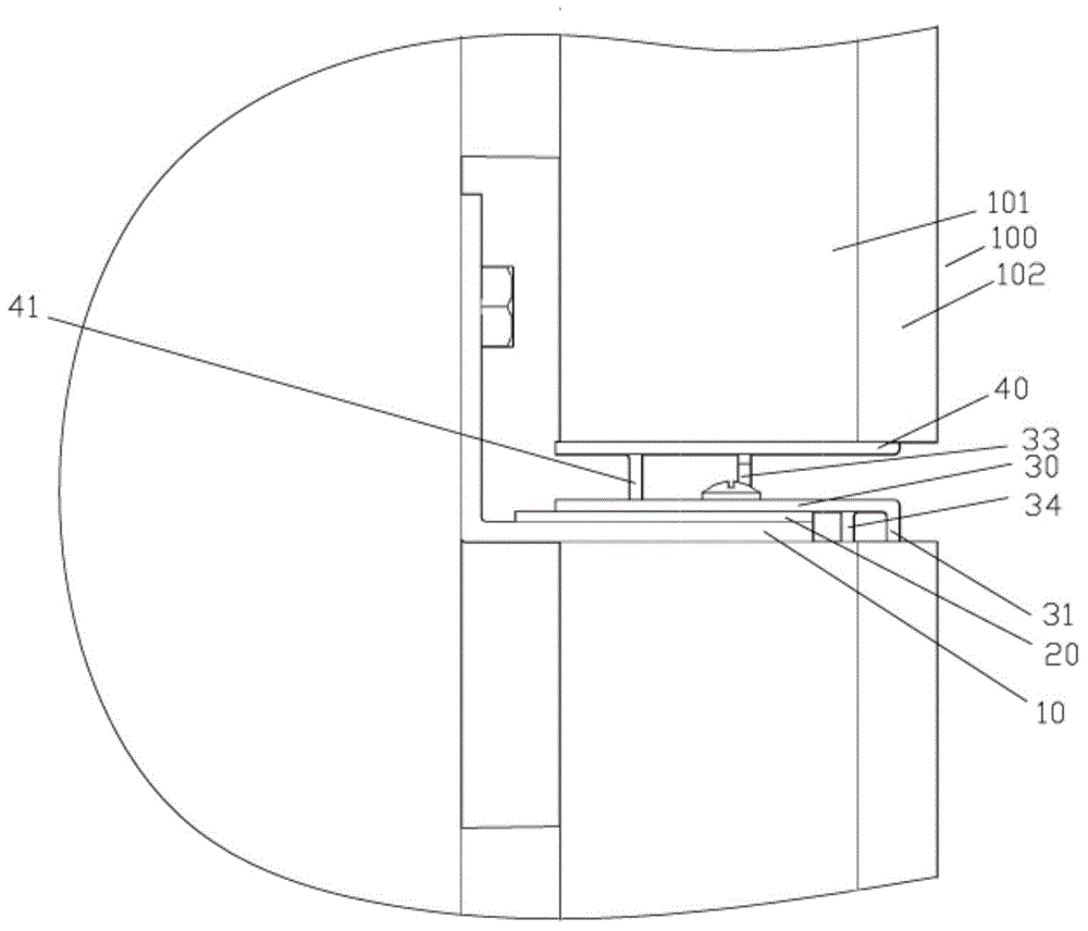
[0021] Examples, see e.g. Figures 3 to 5 As shown, an improved anchor device includes a fixed bracket 10, a thermal break 20 is placed on the top surface of the fixed bracket 10, and the lower fixed piece 30 is fixedly connected to the fixed bracket 10 by bolts, and the heat insulation The piece 20 is clamped between the lower fixing piece 30 and the fixing bracket 10, and the fixing bracket 10 is fixedly connected to the wall surface through fixing bolts, and the front end of the lower fixing piece 30 protrudes from the fixing bracket 10 and is bent...


PUM


Abstract

The invention discloses an improved anchoring part device. The improved anchoring part device comprises a fixing supporting part, a heat insulating piece is arranged on the top face of the fixing supporting part, and a lower fixing piece is fixedly connected to the fixing supporting part through bolts. The heat insulating piece is clamped between the lower fixing piece and the fixing supporting part. The fixing supporting part is fixedly connected to a wall through bolts. The front end of the lower fixing piece extends out of the fixing supporting piece and is bent downwards to form a lower inserting and connecting part, and the middle of the lower fixing piece is provided with a limiting hole and a gap controlling piece bent upwards. The middle of an upper fixing piece is provided with a fixing inserting and connecting piece bent downwards. The fixing inserting and connecting piece is inserted and clamped in a corresponding limiting hole of the lower fixing piece in a sleeving mode. The gap controlling piece is pressed on the bottom face of the upper fixing piece, and the front end of the upper fixing piece is provided with an upper inserting and connecting part bent upwards. The improved anchoring part device is simple in structure and convenient to install, the distance between an upper heat preservation plate and a lower heat preservation plate can be guaranteed, installing requirements for different gap widths are met, and the anchoring strength is guaranteed.

Description

Technical field: [0001] The invention relates to the technical field of building wall connection structures, and more specifically relates to an improved anchor device. Background technique: [0002] Existing wall panel anchors consist of a Z-shaped connector and a butterfly fastener, such as figure 1 and figure 2 As shown, the connection is fixed on the wall by a Z-shaped connector and a butterfly-shaped fastener. The two Z-shaped connectors are on both sides of the insulation board, and the butterfly-shaped fastener is fixed on the upper part of the insulation board. , the butterfly fastener has upward-bending and downward-bending protrusions, and the protrusions are inserted into the corresponding sockets on the insulation board, which cannot adjust the distance between the upper insulation board and the lower insulation board. , At the same time, the Z-shaped connector can only fix the insulation layer of the insulation board, forming a cold and heat bridge, and the d...

Claims


Application Information

Patent Timeline
Patent Type & Authority Applications(China)
IPC IPC(8): E04F13/22E04F13/075
Inventor 王志敏沈巧玲谢雅娟盛建峰曹小飞
Owner ZHEJIANG XINRUIMING DECORATIVE MATERIAL
Learn More