

Spiral-flow type jet pump
A jet pump and swirling technology, applied in the field of jet pumps, can solve the problems of high cost, high difficulty in nozzle processing, and the actual efficiency has not been substantially improved, so as to achieve the effect of increasing the flow rate of the liquid to be sucked and improving the efficiency.
- Summary
- Abstract
- Description
- Claims
- Application Information
AI Technical Summary
Problems solved by technology
Method used
Image

Examples
Embodiment Construction
[0017] The present invention will be further described below in conjunction with accompanying drawing.
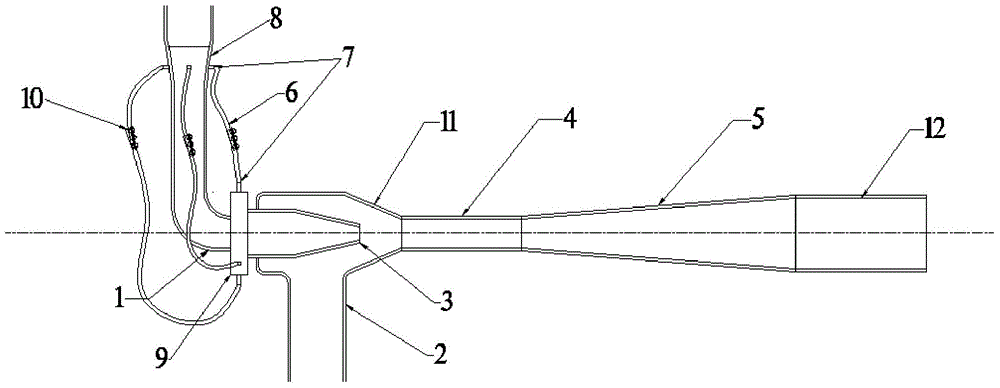
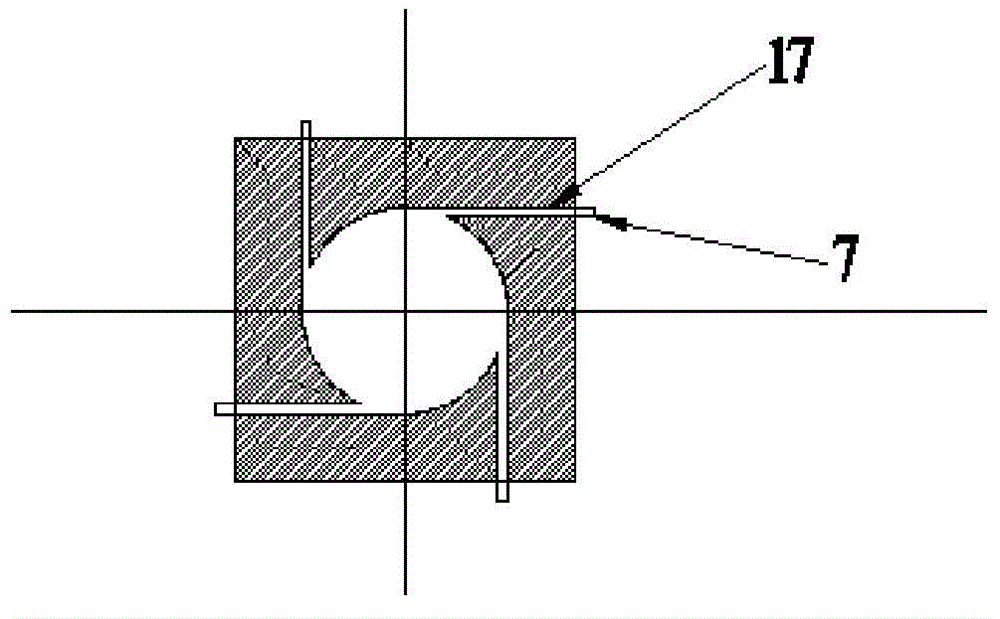
[0018] figure 1 Schematic diagram of the installation of the swirl jet pump, including water inlet pipe 1, swirl generator 9, nozzle 3, throat pipe 4, water suction pipe 2, diffuser pipe 5 and outlet pipe 12, the jet pump is installed in sequence from left to right Water inlet pipe 1, swirl generator 9, nozzle 3, water suction pipe 2, throat pipe 4, diffusion pipe 5 and water outlet pipe 12; one end of the nozzle 3 is installed in the suction chamber 11 of the water suction pipe 2; One end of the water inlet pipe 1 is connected to the swirl generator 9, and the other end is connected to a multi-way pipe 8; the outer wall of the multi-way pipe 8 is radially and uniformly provided with no less than four short pipes 7 of different diameters, so The outer wall of the swirl flow generator 9 is equally radially and uniformly provided with no less than four different-diameter sho...
PUM
 Abstract
Description
Claims
Application Information