Integrated electromagnetic induction steam generation system

An electromagnetic induction and steam generation technology, applied in steam generation, steam generation method, climate sustainability, etc., can solve the problems of unrecyclable reuse, low steam generation efficiency, and small amount of steam generation, so as to improve the generation efficiency, The effect of flexible use and resource saving

Inactive Publication Date: 2015-09-09
宁波波力维革环保设备科技有限公司
View PDF6 Cites 3 Cited by
  • Summary
  • Abstract
  • Description
  • Claims
  • Application Information

AI Technical Summary

Problems solved by technology

[0003] The existing electromagnetic heating steam generating device usually includes a heating tank, a control system, and a water source tank. A conductive coil is wound around the outside of the heating tank, and the control system is electrically connected to the conductive coil. There is a feed water pump, which pumps the water in the water source tank to the heating tank, and the control system energizes the conductive coil. Under the action of the eddy current, the heating tank generates heat by itself, so that the heating tank heats the water inside. To generate steam, usually the heating tank is connected with the gas equipment, and the steam is transported from the heating tank to the gas equipment for use. This traditional electromagnetic heating steam generating device has the following problems: 1. It only has one heating tank, and the steam The amount of generation is small, and the steam generation efficiency is low; 2. The steam is transported to the gas equipment for use through the heating tank, and the steam is usually released after use, and cannot be recycled for reuse, resulting in waste of steam and increasing the corresponding manufacturing cost

Method used


Image

  • Integrated electromagnetic induction steam generation system
  • Integrated electromagnetic induction steam generation system

Examples


Embodiment Construction

[0027] The following are specific embodiments of the present invention and in conjunction with the accompanying drawings, the technical solutions of the present invention are further described, but the present invention is not limited to these embodiments.

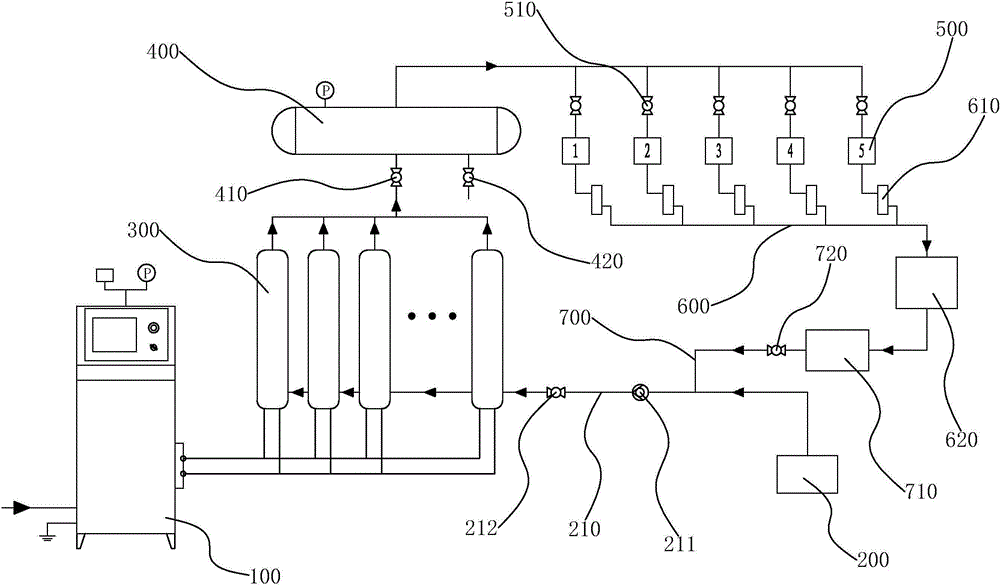
[0028] Such as figure 1 As shown, the integrated electromagnetic induction steam generation system includes a system controller 100, a water source tank 200, a steam generation unit, a gas collection unit, a gas consumption unit, and a recovery unit.

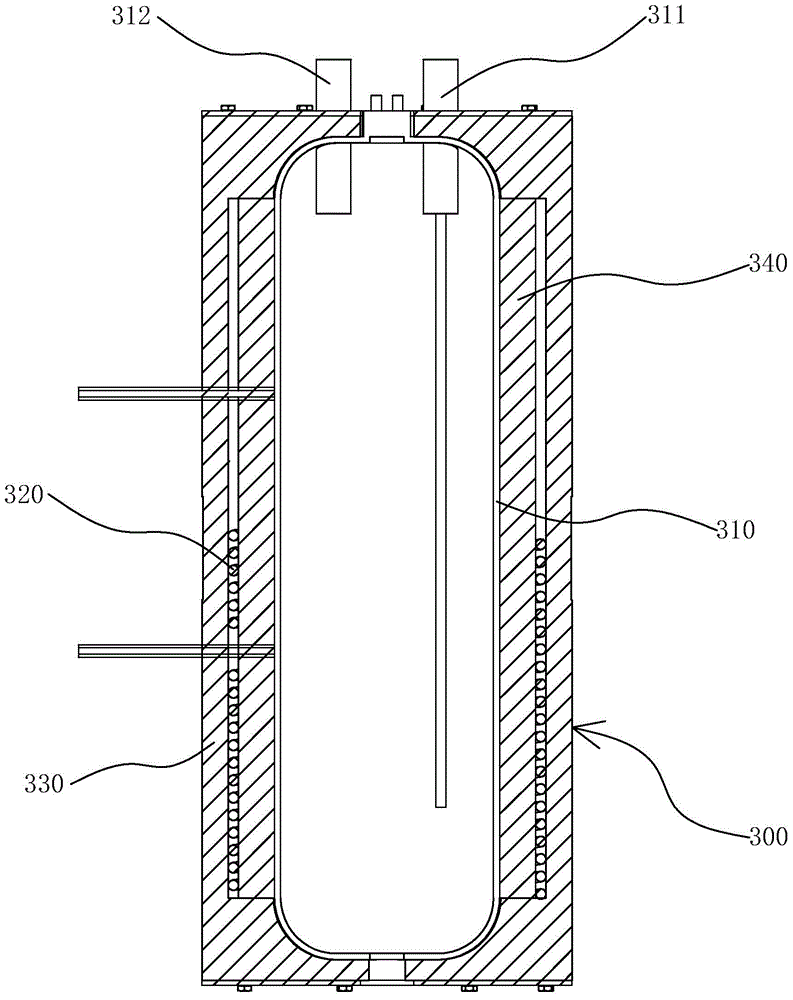
[0029] The steam generating unit includes a plurality of gas-making furnace bodies 300 connected in parallel and used to generate steam, such as figure 2 As shown, each gas-making furnace body 300 includes a gas-making furnace 310 and a conductive coil 320. The gas-making furnace 310 is empty and filled with water inside. The gas-making furnace 310 is provided with a water inlet 311 and an outlet. The gas pipe 312 and the conductive coil 320 are wound outside the gas-makin...


PUM


Abstract

The invention provides an electromagnetic induction steam generation system and belongs to the steam manufacturing technical field. The technical problems that the existing steam generation device is low in steam generation efficiency and large in steam waste degree are solved. According to the technical scheme, the electromagnetic induction steam generation system comprises a steam generation unit, a steam collection unit, a steam unit and a recovery unit; the steam generation unit comprises a plurality of parallel steam generation furnace bodies which are used for generating the steam; the steam collection unit is communicated with every steam generation furnace body; the steam in every steam generation furnace body is output to the steam collection unit to be concentrated; the steam unit comprises a plurality of steam devices which are communicated with the steam collection unit; the recovery unit is communicated with the steam devices and the steam generation furnace bodies; the steam flows to the steam generation furnace bodies through the recovery unit. According to the electromagnetic induction steam generation system, the steam is simultaneously manufactured through the plurality of steam generation furnace bodies and accordingly the generation of the steam within every unit time is increased and the generation efficiency of the steam is improved and the waste is avoided due to the fact that the steam utilized through the steam devices is recycled through the recovery unit.

Description

technical field [0001] The invention belongs to the technical field of steam production, and relates to an electromagnetic induction steam generation system, in particular to an integrated electromagnetic induction steam generation system composed of a plurality of tanks. Background technique [0002] Steam generating devices are widely used in the current industrial and commercial fields. For example, factories, heating, hotels and other occasions require boiler equipment such as steam and hot water. With the development of this application, electromagnetic induction heating has gradually replaced traditional coal-fired Heating methods such as heating have less energy consumption, higher energy utilization, and are more environmentally friendly. [0003] The existing electromagnetic heating steam generating device usually includes a heating tank, a control system, and a water source tank. A conductive coil is wound around the outside of the heating tank, and the control sys...

Claims


Application Information

Patent Timeline
Patent Type & Authority Applications(China)
IPC IPC(8): F22B1/28
CPCY02P80/15
Inventor 秦柳叶沼汝王国栋虞华春
Owner 宁波波力维革环保设备科技有限公司
Why Eureka
Try Eureka