Mesh subdivision method based on laplacian coordinates

A grid subdivision and target grid technology, applied in image data processing, 3D modeling, instruments, etc., can solve the problem of no analytical form and complexity of subdivided surfaces

Inactive Publication Date: 2015-09-09
HAINAN NORMAL UNIV
View PDF3 Cites 8 Cited by
  • Summary
  • Abstract
  • Description
  • Claims
  • Application Information

AI Technical Summary

Problems solved by technology

The subdivision surface has no analytical form, and the continuity and smoothness analysis of the surface is v

Method used


Image

  • Mesh subdivision method based on laplacian coordinates
  • Mesh subdivision method based on laplacian coordinates
  • Mesh subdivision method based on laplacian coordinates

Examples


Embodiment Construction

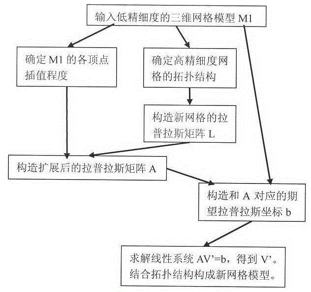
[0021] The present invention will be further described below in conjunction with the accompanying drawings.

[0022] First, input a low-precision 3D mesh model and set it to M1. It includes the set of vertices V={v0,v1,...,vi,...}, the set of edges E={e0,e1,...,ej,...}, and the set of faces F={f0,f1,...,fk,... }. May wish to set the number of vertices to N.

[0023] In order to determine the degree of interpolation or approximation of each vertex in V, it is necessary to determine an approximation value cvi for each vertex vi. This value can be any positive number. When the value is larger, it means that the corresponding vertices in the new grid are closer to the original vertices, that is, closer to the interpolation. When the value is infinite, the original vertex is interpolated. When the value is smaller, it means that the point is more free, and its position is determined by the smooth factor.

[0024] The user can specify the interpolation degree value in the follo...


PUM


Abstract

The invention provides a mesh subdivision method based on laplacian coordinates, relates to the technology of three-dimensional mesh model modeling and subdivision, and particularly relates to the technology of maintenance of enhancement of fineness of three-dimensional mesh model specific characteristics. With increasing development of computer hardware, multiple computer graphical applications use complex models with high-fineness detail information so as to realize high sense of reality, and the construction of the high-fineness mesh models cannot meet the requirements. The mesh subdivision method is put forward to facilitate work of the aspect. Based on a low-fineness mesh model, the degree of interpolation of a vertex and the topological structure of a new mesh are confirmed by a user, and then an extended laplacian matrix and the corresponding expected laplacian coordinates are constructed to form a linear system so that the position of the vertex of the new mesh is solved. Finally, a new high-fineness mesh model is constructed through combination of the topological structure. The concrete realization process is shown in the appended drawings.

Description

technical field [0001] The invention relates to the modeling and subdivision technology of a three-dimensional grid model, in particular to the fineness improvement technology for maintaining the specified characteristics of the three-dimensional grid model. Background technique [0002] At present, in computer graphics, with the continuous development of computer hardware, graphics processing capabilities are getting stronger and stronger. In order to achieve high realism, many computer graphics applications use complex models with high-precision detail information. Therefore, the construction of commonly used models often requires high precision. Although there are technologies such as 3D scanning to obtain high-density vertices at one time, scanning alone cannot satisfy people's growing demand for 3D models. Then, people need to use various tools to design models according to their own ideas. Directly determining the vertices of the high-precision model one by one is a ...

Claims


Application Information

Patent Timeline
IPC IPC(8): G06T17/30
Inventor 邓正杰石春何书前
Owner HAINAN NORMAL UNIV
Why Eureka
Try Eureka