Multifunctional coupler

A coupler and multi-functional technology, applied in the field of couplers, can solve the problems of high assembly requirements, high production costs, and high processing precision, and achieve the effect of little change in standing waves, lower processing precision, and small fluctuation range

Inactive Publication Date: 2015-09-09
HEFEI JIARUILIN ELECTRONICS TECH
View PDF2 Cites 8 Cited by
  • Summary
  • Abstract
  • Description
  • Claims
  • Application Information

AI Technical Summary

Problems solved by technology

[0002] The frequency of the widely used cavity directional coupler is between 800-2500MHz, which covers the main frequency of mobile communication, and also covers the general frequency of 3G. Due to the popularization of digital TV, the original analog signal gradually cancels the frequency of 700MHz. The frequency is likely to be used in 3G products. If you want to cover the whole band, you need a coupler and a power splitter with a wider bandwidth, so that you can cover more frequency bands. The existing couplers generally use columnar coupling. Although it can cover more frequency bands, it greatly limits the application of this type of product due to its shortcomings such as high production cost, high processing precision, and high assembly requirements.

Method used


Image

  • Multifunctional coupler

Examples


Embodiment Construction

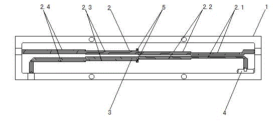
[0011] refer to figure 1 , a multifunctional coupler, which is composed of a housing 1, a coupling straight rod 2, a coupling curved rod 3, a resistor 4, and a debugging block 5. The coupling straight rod 2 and the coupling bending rod 3 are arranged in the cavity of the housing 1, Both ends of the coupling straight rod 2 can be connected to the outside through the casing 1, one end of the coupling curved rod 3 can be connected to the outside through the casing 1, and the other end is connected to the resistor 4. The coupling straight rod 2 and the coupling curved rod 3 are connected One debug block 5 is provided respectively.

[0012] The straight coupling rod 2 and the curved coupling rod 3 are respectively composed of a first-level coupling area 2.1, a second-level coupling area 2.2, a third-level coupling area 2.3, and a fourth-level coupling area 2.4.

[0013] The debugging block 5 is respectively arranged at the front end of the third-level coupling area 2.3 of the coup...


PUM


Abstract

The utility model discloses a multifunctional coupler, relating to the technical field of couplers. The multifunctional coupler comprises a housing, a coupling straight bar, a coupling curved bar, a resistor and a debugging block, wherein the coupling straight bar and the coupling curved bar are arranged in a cavity of the housing, the two ends of the coupling straight bar are connected with the outside through the housing, one end of the coupling curved bar is connected with the outside through the housing, and the other end of the coupling curved bar is connected with the resistor. The four-stage strip line cavity directional coupler disclosed by the utility model adopts a coupling strip line four-stage design and can not only meet the requirements of an ordinary cylindrical coupler for covering bandwidth, but also reduce the precision, assembly requirements and production cost which are required by processing during production processes.

Description

technical field [0001] The invention relates to the technical field of couplers, in particular to an air cavity stripline coupler. Background technique [0002] The frequency of the widely used cavity directional coupler is between 800-2500MHz, which covers the main frequency of mobile communication, and also covers the general frequency of 3G. Due to the popularization of digital TV, the original analog signal gradually cancels the frequency of 700MHz. The frequency is likely to be used in 3G products. If you want to cover the whole band, you need a coupler and a power splitter with a wider bandwidth, so that you can cover more frequency bands. The existing couplers generally use columnar coupling. Although the design can cover more frequency bands, its disadvantages such as high production cost, high processing precision, and high assembly requirements greatly limit the application of this type of product. Contents of the invention [0003] The purpose of the present ...

Claims


Application Information

Patent Timeline
Patent Type & Authority Applications(China)
IPC IPC(8): H01P5/18
Inventor 岳朝风
Owner HEFEI JIARUILIN ELECTRONICS TECH
Why Eureka
Try Eureka