Laser machine

A laser machine and laser technology, applied in auxiliary devices, laser welding equipment, auxiliary welding equipment, etc., can solve problems such as low efficiency, achieve the effects of improving efficiency, shortening waiting time, and realizing cycle automation

Inactive Publication Date: 2015-09-16
SHENZHEN FUTAIHONG PRECISION IND CO LTD
View PDF7 Cites 1 Cited by
  • Summary
  • Abstract
  • Description
  • Claims
  • Application Information

AI Technical Summary

Problems solved by technology

Existing laser equipment usually uses a fixed carrier. Each time the operator needs to wait for the previous product to complete the laser process, the operator can carry out the next loading, which is inefficient

Method used


Image

  • Laser machine
  • Laser machine
  • Laser machine

Examples


Embodiment Construction

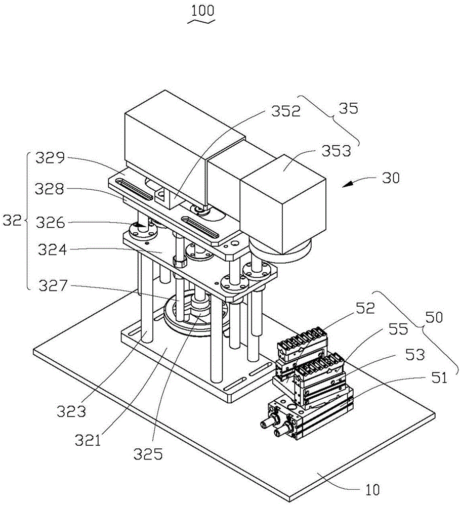
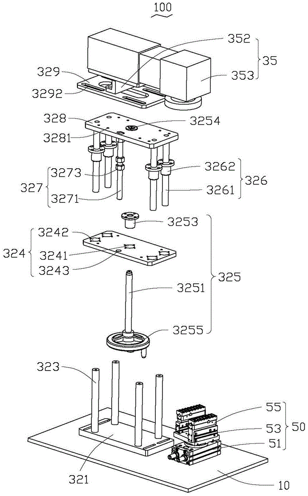
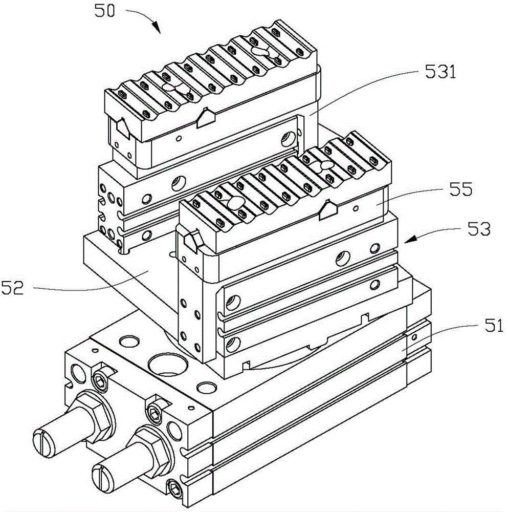
[0012] See figure 1 The preferred embodiment of the present invention provides a laser machine 100, which is used for laser marking or welding processes. In this embodiment, the laser machine 100 is applied to a marking process for description. The laser machine 100 includes a worktable 10, a laser device 30 and an object carrying device 50. The laser device 30 and the object carrying device 50 are installed on the workbench 10 opposite to each other. The workbench 10 can install at least one set of the laser device 30 and the object carrier 50. Both the laser device 30 and the object carrying device 50 are connected to an electric control box (not shown).

[0013] Please refer to figure 2 , The laser device 30 is used to generate laser light. The laser device 30 includes an adjusting component 32 and a laser component 35. The adjusting component 32 is used to adjust the position of the laser component 35. The adjusting assembly 32 includes a base 321, a plurality of support...


PUM


Abstract

The invention proposes a laser machine for a laser marking or welding process. The laser machine comprises a laser device and a loading device oppositely arranged, wherein the laser device comprises a laser component for generating laser light rays. The laser machine is characterized in that the laser device further comprises an adjusting component; the adjusting component is connected to the laser device, and is used for adjusting the position of the laser component; the loading device comprises a rotating cylinder, a transfer plate, two extension cylinders and two tools; one surface of the transfer plate is mounted on the rotating cylinder, and the other surface bears the two extension cylinders; the transfer plate is used for driving the two extension cylinders to rotate under the driving of the rotating cylinder; and the two tools are used for bearing products, and are mounted on the corresponding extension cylinders for moving in opposite directions under the driving of the two extension cylinders. The laser machine is high in efficiency.

Description

Technical field [0001] The invention relates to a laser machine, in particular to a laser machine used for laser marking and welding. Background technique [0002] Laser technology is widely used in modern production processes. By installing a laser head on the machine, laser carving, welding, and laser marking can be performed. The existing laser equipment usually uses a fixed carrier, and the operator must wait for the previous product to complete the laser process for each job, and the operator can carry out the next loading, which is inefficient. Summary of the invention [0003] In view of the above problems, it is necessary to provide a laser machine that can improve working efficiency. [0004] A laser machine includes a laser device and an object-carrying device that are arranged oppositely. The laser device includes a laser component for generating laser light. The laser device further includes an adjustment component connected to the laser device. To adjust the position...

Claims


Application Information

Patent Timeline
Patent Type & Authority Applications(China)
IPC IPC(8): B23K26/00B23K26/035B23K26/70
CPCB23K26/352B23K37/047
Inventor 李清泉张振华李明
Owner SHENZHEN FUTAIHONG PRECISION IND CO LTD
Why Eureka
Try Eureka