Eureka AIR delivers breakthrough ideas for toughest innovation challenges, trusted by R&D personnel around the world.

Backward steering device for propelling and direction control in water

A steering device and direction control technology, which is applied to steering and other directions with propulsion components, can solve the problems of heavy weight, high cost, large volume, etc., and achieve the effect of reducing installation.

Inactive Publication Date: 2015-09-16
黄塬森
View PDF9 Cites 1 Cited by
  • Summary
  • Abstract
  • Description
  • Claims
  • Application Information

AI Technical Summary

Problems solved by technology

[0006] For the ships involved in the above prior art, due to the many parts involved, the whole ship is large in size, heavy in weight, complex in structure, inconvenient for daily maintenance, and relatively high in cost. It is too fast, and if turning in situ is to be realized, the water jets need to be symmetrically distributed in structure. At the same time, the size of the retrograde rudder installed will be limited by the turning angle of the turning rudder

Method used


Image

  • Backward steering device for propelling and direction control in water
  • Backward steering device for propelling and direction control in water
  • Backward steering device for propelling and direction control in water

Examples


Embodiment 1

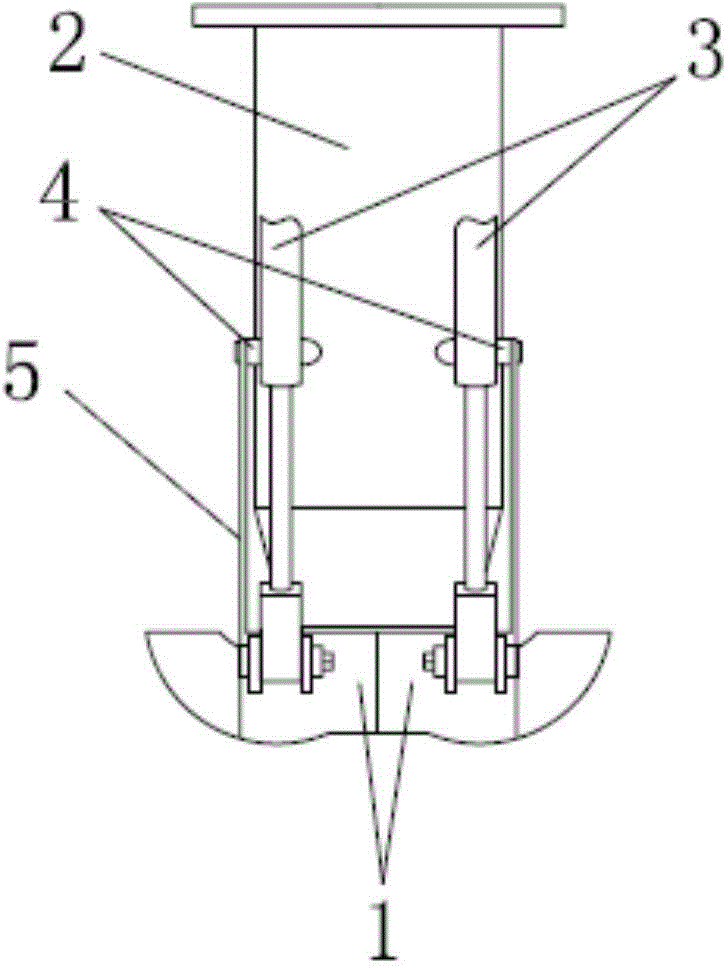
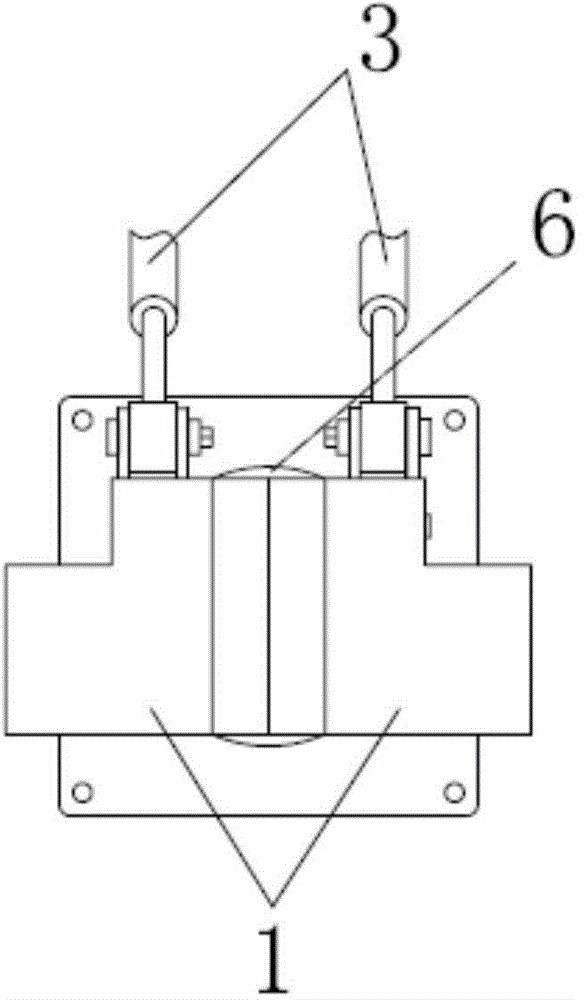
[0049] Such as figure 1 As shown, this embodiment discloses a reverse steering device for underwater propulsion and direction control, which includes a rudder 1 , a water jet 2 and a displacement device 3 .

[0050] Wherein, the number of the water jet propeller 2 is one. They are provided as a pair, and are symmetrically distributed on both sides of the vertical central axis of the water spout 6 . At the same time, each rudder 1 is connected to a shifting device 4, which is represented by a telescopic mechanism in this embodiment, and adopts hydraulic pressure, push-pull shaft or electric mode for telescopic operation, and is intended to drive the rudder 1 to deviate or Returns to the outside of the spout, but other mechanisms that serve the same purpose could be substituted.

[0051] Among them, the rudder is symmetrically distributed on the vertical central axis of the water nozzle, the purpose is to make the displacement device connected with it and give the push-pull fo...

Embodiment 2

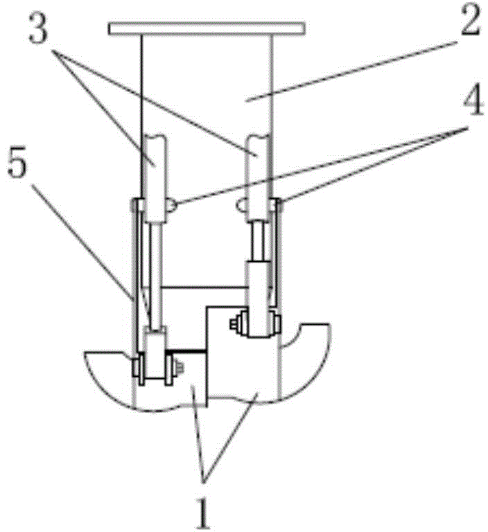
[0060] The difference between this embodiment and Embodiment 1 is that the rudder 1 is arranged laterally on both sides of the vertical central axis of the water jet 6 of the water jet propeller 2 through the connecting strut 5 . Since the reverse rudder 1 is arranged laterally, the hinge point 4 is located at the middle and lower part of the outer wall of the water jet propeller 2 .

[0061] The reason why the hinge point 4 is arranged on the middle and lower part of the water jet propeller 2 outer walls is that the reverse rudder 1 is arranged on the longitudinal plane of the water nozzle 6 in a horizontal manner, because the reverse rudder 1 is moving During the push-pull process of the positioning device 3, since its own length is relatively small in the horizontal dimension relative to the longitudinal dimension, when it is necessary to change the force of the sprayed water from the water spout 6 on the reverse rudder 1, the reverse rudder 1 is in the Deflection on the su...

Embodiment 3

[0067] The only difference between this embodiment and Embodiment 1 is that the rudder 1 on the left side is arranged laterally, so the corresponding hinge point 4 is arranged in the middle and lower part of the water jet propeller 2, as Figure 9 As shown, the reverse rudders 1 connected to the two water jets 2 are connected in different ways, and the principle of setting the hinge point 4 there is the same as that of Embodiment 2, and will not be repeated here. . Of course, it is also possible that the rudder positioned on the left side is arranged longitudinally, and the rudder 1 positioned on the right side is arranged horizontally.

[0068] Depend on Figure 9It can be seen that it shows the state of turning counterclockwise in situ, the left rudder 1 does not deviate from the water nozzle 6, and the right rudder 1 completely deviates from the water nozzle 6, so the water flow on the left is moved forward by the rudder 1 The water flow on the right side is sprayed direc...


PUM


Abstract

The invention discloses a backward steering device for propelling and direction control in water. The backward steering device comprises a water spraying propeller, at least two rudders and shift devices, wherein the rudders are respectively arranged on the outer sides of a water spraying opening of the water spraying propeller and used for changing the flow direction of water sprayed by the water spraying propeller; the shift devices are respectively connected with the rudders and used for driving the rudders to deviate from and return to the outer sides of the water spraying opening of the water spraying propeller; one of the water spraying propellers is arranged, and correspondingly a pair of the rudders is arranged and relatively distributed on two sides of a vertical axle wire of the water spraying opening. According to the backward steering device for the propelling and the direction control in water, disclosed by the invention, during the rudders are reduced, a left turn function, a right turn function, a left turn in situ function, a right turn in situ function and a drawing back function can also be realized, so that parts and components are greatly reduced, besides the size is reduced, the weight is lightened, the speed is accelerated, the routine maintenance is convenient, and the related cost is relatively lower.

Description

technical field [0001] The invention belongs to the technical field of ship equipment, and in particular relates to a reverse steering device for underwater propulsion and direction control. Background technique [0002] At present, when a ship propelled by an existing water jet propeller needs to turn, the turning rudder deflects to the left or right, thereby realizing the left or right turn of the ship. In practice, the waterjet is generally installed below the waterline of the ship, and the water flow usually passes below two-thirds of the height of the waterjet when traveling, and the concave-convex gap formed between the waterjet and the turning rudder, Just around the height of the entire water jet propeller, a certain impact force is formed when the water flow passes through the turning rudder, resulting in a decrease in travel speed and an increase in energy consumption. Therefore, in order to reduce the impact force caused by the water flow to the turning rudder wh...

Claims


Application Information

Patent Timeline
Patent Type & Authority Applications(China)
IPC IPC(8): B63H25/42
Inventor 黄塬森
Owner 黄塬森
Why Eureka
Eureka Blog
Learn More