Constant-torque integral broken belt catching device and catching method thereof

A broken belt catching device and integrated technology, applied in the conveyor control device, transportation and packaging, conveyor and other directions, can solve the problems of many fault points, local bolt breakage, easy to produce malfunction and so on, to facilitate on-site construction. , Avoid secondary belt breakage and ensure the effect of reliability

Active Publication Date: 2015-09-16
SHANDONG VICTEUR MECHANICAL & ELECTRICAL TECH
View PDF6 Cites 3 Cited by
  • Summary
  • Abstract
  • Description
  • Claims
  • Application Information

AI Technical Summary

Problems solved by technology

The hydraulic integral arresting device system is complicated, there are many fault points, and it is difficult to arrange high-pressure oil pipes along the line, and the energy consumption is high, and the trigger is easy to cause malfunction when the tape slides down to catch
After the triggering of the mechanical overall capture device, the torque varies with the angle and is not constant. The capture shoe is in point and line contact, which may easily cause the loss of the tape and cause a secondary broken belt accident. The capture beam and the side frame are connected by bolts. The bolts are stressed during fishing, and local bolts will break when they are sheared, which brings danger to the use of equipment

Method used


Image

  • Constant-torque integral broken belt catching device and catching method thereof
  • Constant-torque integral broken belt catching device and catching method thereof
  • Constant-torque integral broken belt catching device and catching method thereof

Examples


Embodiment Construction

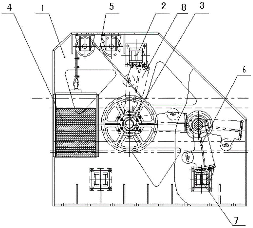
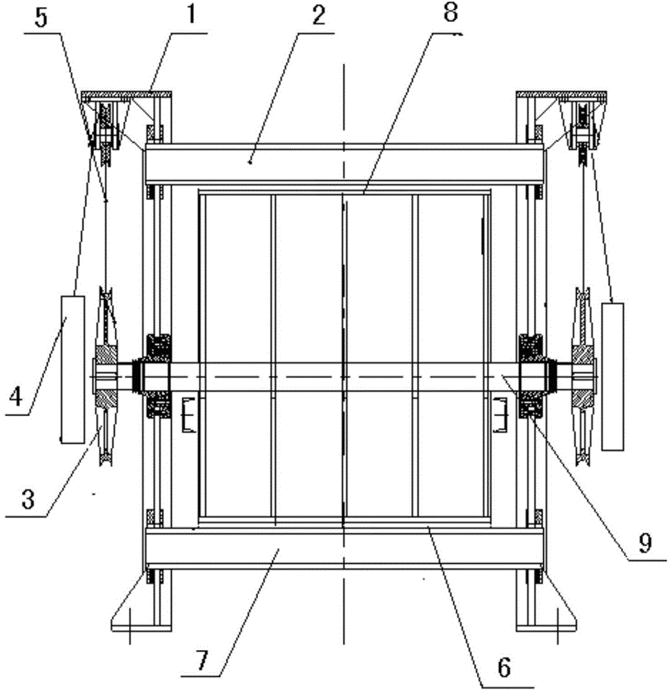
[0028] Such as figure 1 , 2 As shown in Figure 3, a constant-torque integrated belt-breaking catching device is composed of a frame 1, an upper beam 2, a lower beam 7, a rotating shaft 9, an upper capture frame 8, a lower capture frame 6 and a drive system;

[0029] The frame 1 is a three-dimensional frame straddling the belt conveyor;

[0030] The upper beam 2 and the lower beam 7 are respectively fixed on the upper and lower parts of the frame 1, thereby forming a frame-type closed-loop structure;

[0031] The rotating shaft 9 is installed on the frame 1 across the middle of the frame 1;

[0032] The upper catch frame 8 is installed on the rotating shaft 9. The upper catch frame 8 rotates upward and corresponds to the bottom surface of the upper cross beam 8. When the upper catch frame 8 rotates to the bottom surface of the upper cross beam 8, a pair of conveyor belts can be formed. Band clamping force;

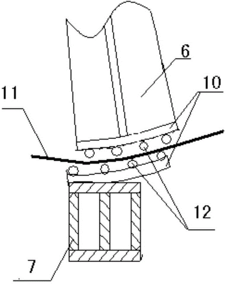
[0033] The lower catch frame 6 is hinged on the frame 1 with its rotating surfa...


PUM


Abstract

The invention discloses a constant-torque integral broken belt catching device and a catching method thereof. The broken belt catching device consists of a rack, an upper cross beam, a lower cross beam, a rotating shaft, an upper catching rack, a lower catching rack and a driving system, wherein the upper cross beam and the lower cross beam are respectively and fixedly arranged on the upper and lower parts of the rack; the rotating shaft transversely penetrates through the middle of the rack and is arranged on the rack; the upper catching rack is arranged on the rotating shaft and corresponds to the bottom surface of the upper cross beam; the rotating surface of the lower catching rack is downwards articulated with the rack and corresponds to the top surface of the lower cross beam; the driving system consists of two symmetrically-arranged steel wire ropes, two symmetrically-arranged sheave wheels and two symmetrically-arranged weight boxes; the upper catching rack is driven to rotate under the gravity action of the weight box, so that a broken upper-layer rubber belt is supported and clamped, and thus rubber belt catching is realized. When belt breakage occurs, the rubber belt is suddenly accelerated after relaxation, and the upper catching rack and the lower catching rack are triggered to across a dead point so as to rotate respectively towards the upper cross beam and the lower cross beam, so that the rubber belt is rapidly caught. The constant-torque integral broken belt catching device is rapid and accurate in response and free from incorrect action.

Description

Technical field [0001] The invention relates to a belt conveyor, in particular to a belt-breaking catching device of the belt conveyor. Background technique [0002] The existing belt-breaking catching devices are divided into two-ear catching devices, hydraulic integral catching devices and mechanical integral catching devices. The two-ear type is decentralized capture, with low capture power and easy to malfunction. The hydraulic integrated capture device has a complicated system, with many failure points and high-pressure oil pipes along the line. It is difficult to arrange high energy consumption, and it is easy to cause misoperations when triggered by the belt sliding down to capture. After the mechanical integrated capture device is triggered, the torque changes with the angle and is not constant. The capture shoe is in point and line contact, which is likely to cause the loss of the tape and cause a secondary broken belt. The capture beam and the side frame are connected ...

Claims


Application Information

Patent Timeline
IPC IPC(8): B65G43/06
CPCB65G43/06B65G2203/0275
Inventor 周连富陈新永朱小平
Owner SHANDONG VICTEUR MECHANICAL & ELECTRICAL TECH
Why Eureka
Try Eureka