Computerized flat knitting machine tucking connecting needle pressing leg driving device

A computerized flat knitting machine and transmission device technology, applied in knitting, weft knitting, textiles and papermaking, etc., can solve problems such as low work efficiency, achieve the effects of increasing service life, improving work efficiency, and reducing workload

Active Publication Date: 2015-09-16
ZHEJIANG FENGFAN NC MACHINERY
View PDF6 Cites 3 Cited by
  • Summary
  • Abstract
  • Description
  • Claims
  • Application Information

AI Technical Summary

Problems solved by technology

[0004] The invention provides a transmission device for tucking needles and pressing legs of a computerized flat knitting machine, which solves the problem of low working efficiency of the transmission device for computerized flat knitting machines tucking and connecting needles and pressing legs in the prior art

Method used


Image

  • Computerized flat knitting machine tucking connecting needle pressing leg driving device
  • Computerized flat knitting machine tucking connecting needle pressing leg driving device
  • Computerized flat knitting machine tucking connecting needle pressing leg driving device

Examples


Embodiment Construction

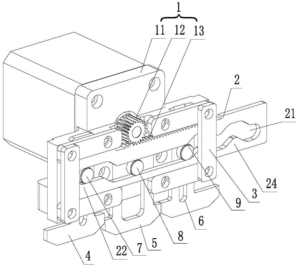
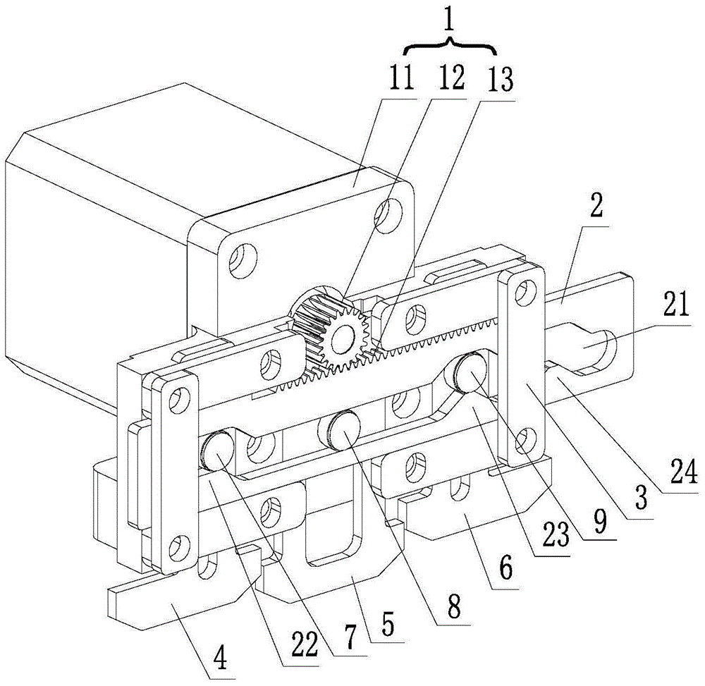
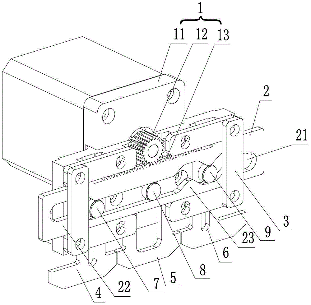
[0018] refer to Figure 1 to Figure 7 , a transmission device for computerized flat knitting machine tucking needle pressing legs, comprising a driving device 1, a movable plate 2, a fixed seat 3, a left needle pressing leg 4, a tucking pressing leg 5, a right needle pressing leg 6, a left The block 7, the middle block 8 and the right block 9; the movable plate 2 is connected with the driving device 1; the fixed seat 3 is provided with a transverse track 31 matching the movable plate 2; the fixed seat 3 is from left to Three longitudinal rails 32 are arranged on the right, and the left needle pressing leg 4, the tuck eye pressing leg 5, and the right needle pressing leg 6 are sequentially installed in the three longitudinal rails 32 from left to right; the left clamping block 7, the middle clamping block 8 and the right block 9 are fixedly connected to the upper end of the left needle presser leg 4, the upper end of the tuck presser leg 5 and the upper end of the right needle ...


PUM


Abstract

The invention provides a computerized flat knitting machine tucking connecting needle pressing leg driving device. The problem of low efficiency of the tucking connecting needle pressing leg driving device in the prior art is solved. The device comprises a moveable plate, a left clamping block, a middle clamping block and a right clamping block; a bar hole is formed in the moveable plate; the bar hole is sequentially provided with a left convex block, a middle convex block and a right convex block from left to right; when the left clamping block is positioned on the most left side of the upper end of the left convex block, the right clamping block is positioned on the right side of the middle convex block; when the left clamping block is positioned on the most right side of the upper end of the left convex block, the right clamping block is positioned at the upper end of the middle convex block; when the right clamping block is positioned between the middle convex block and the right convex block or positioned at the upper end of the right convex block, the left clamping block and the middle clamping block are both positioned between the left convex block and the middle convex block; when the middle clamping block is positioned at the upper end of the middle convex block, the left clamping block is positioned between the left convex block and the middle convex block, and the right clamping block is positioned on the right side of the right convex block. The device provided by the invention has five stations; the action which is finished by the device with three stations at two times can be finished by the device provided by the invention at one time, so that the working efficiency is improved.

Description

technical field [0001] The invention relates to a transmission device for a computerized flat knitting machine tucking needle and pressing leg. Background technique [0002] With the improvement of people's living standards, there are high requirements for the quality of knitted clothes, so the requirements for computerized flat knitting machines are also getting higher and higher. In the computerized flat knitting machines currently on the market, the actions of the tuck presser and the needle presser are driven by electromagnets, but due to the life of the electromagnet itself and the actions of the tuck presser and the contact presser Relatively strict, so the structure using the electromagnet is not very stable, it is easy to reduce the quality of the fabric and cause economic losses. [0003] The prior art closest to the present invention is the transmission mechanism of flat knitting machine tuck and needle press leg disclosed in application number 201220211831.X; but...

Claims


Application Information

Patent Timeline
Patent Type & Authority Applications(China)
IPC IPC(8): D04B15/96
Inventor 傅建新徐登波朱海龙
Owner ZHEJIANG FENGFAN NC MACHINERY
Why Eureka
Try Eureka